2023-02-04: While continuing the reverse engineering of the Milwaukee M18 batteries, It quickly became apparent that I needed to work on some accessories that go with it. While I have a pile of dead batteries, I seem to have a scarcity of chargers... And this particular model is not one that I can completely destroy while pursuing knowledge...
As always, clicking on an image will give you a higher-res version! If you repost or further dissect this board, please link back to the original and let us know where we can read about your work!
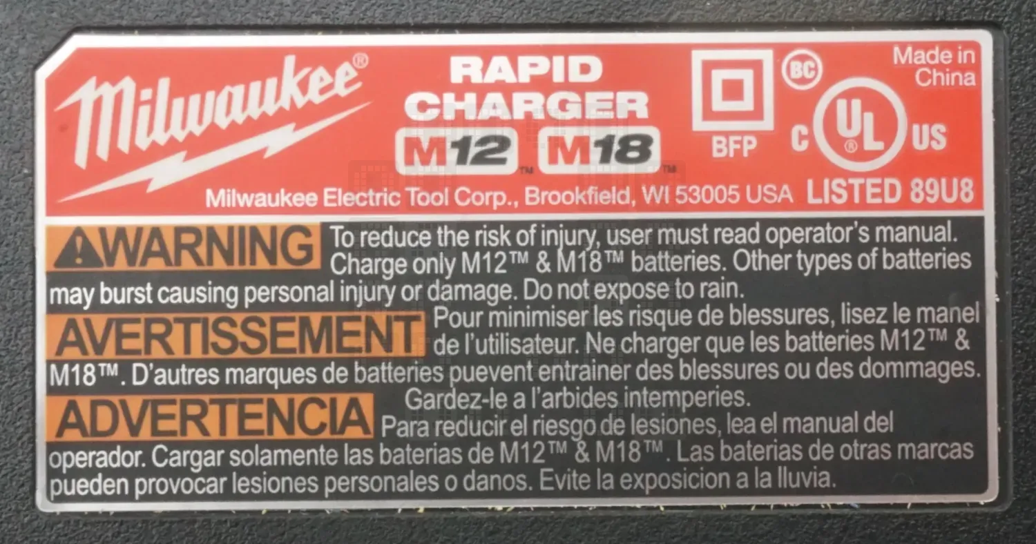
Here is the nameplate on the bottom of the unit. No part number that I notice. Stupidly, I neglected to take any pictures of the outside of the unit in my haste...I may have to update this part later.
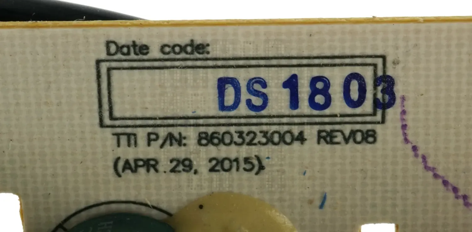
Inside the unit on the circuit board, we see this info: TTI P/N 860323004 Revision 08 (April 29, 2015) with Date Code DS1803 (I assume this is 2018, 3rd Week?)
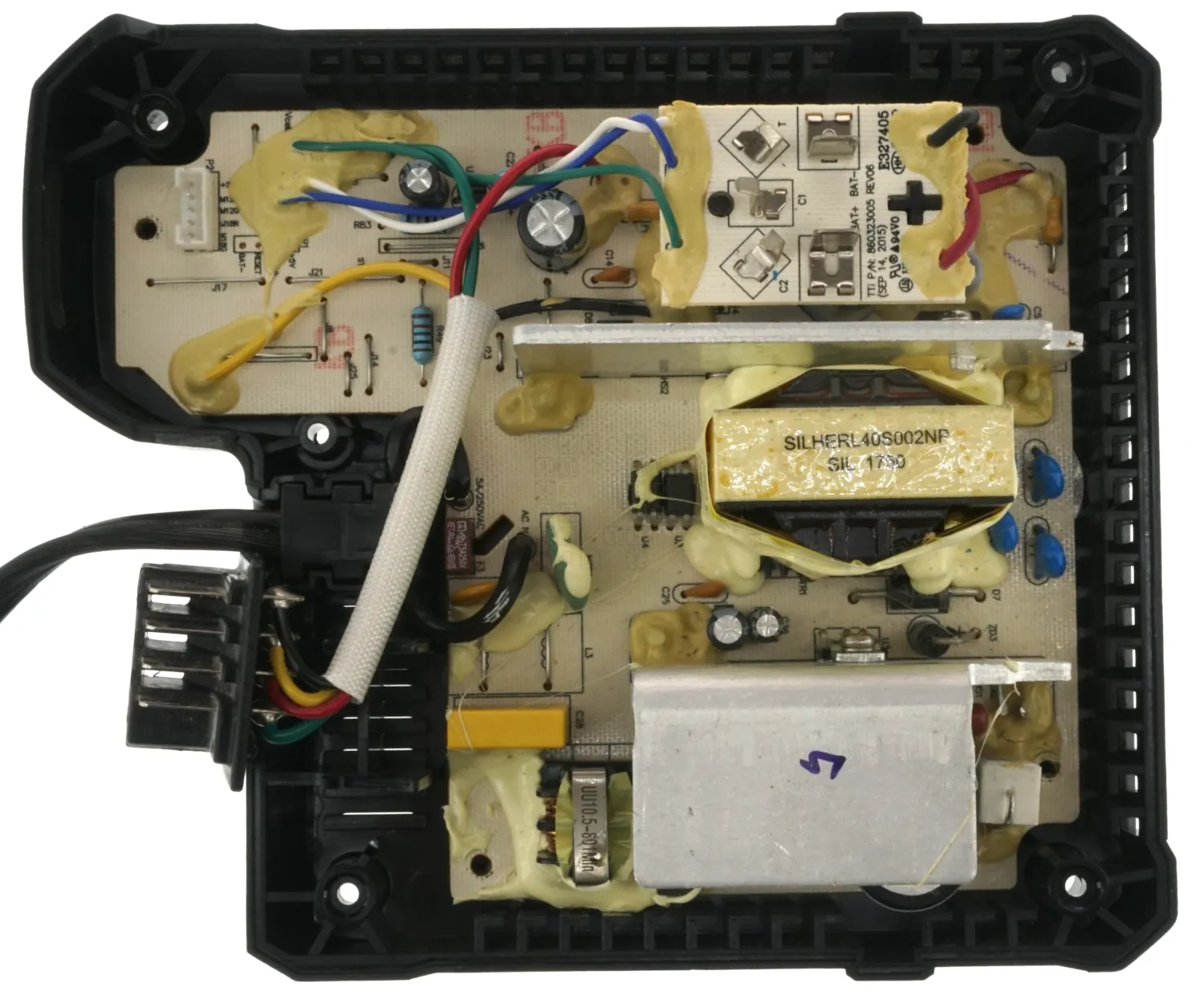
This is a picture of the top of the charger circuit board. I really wanted to remove the glue, but this one needs to go back together again for now. There is a white 5 pin connector in the upper left that attaches to the charging indicator lights which attach to a circuit board on the top casing. Its a simple board - 4 LEDs. There appears to be a 4-Pin programming header half covered by glue right beside this connector though... Board identification (picture above) is hidden under the M12 riser board.
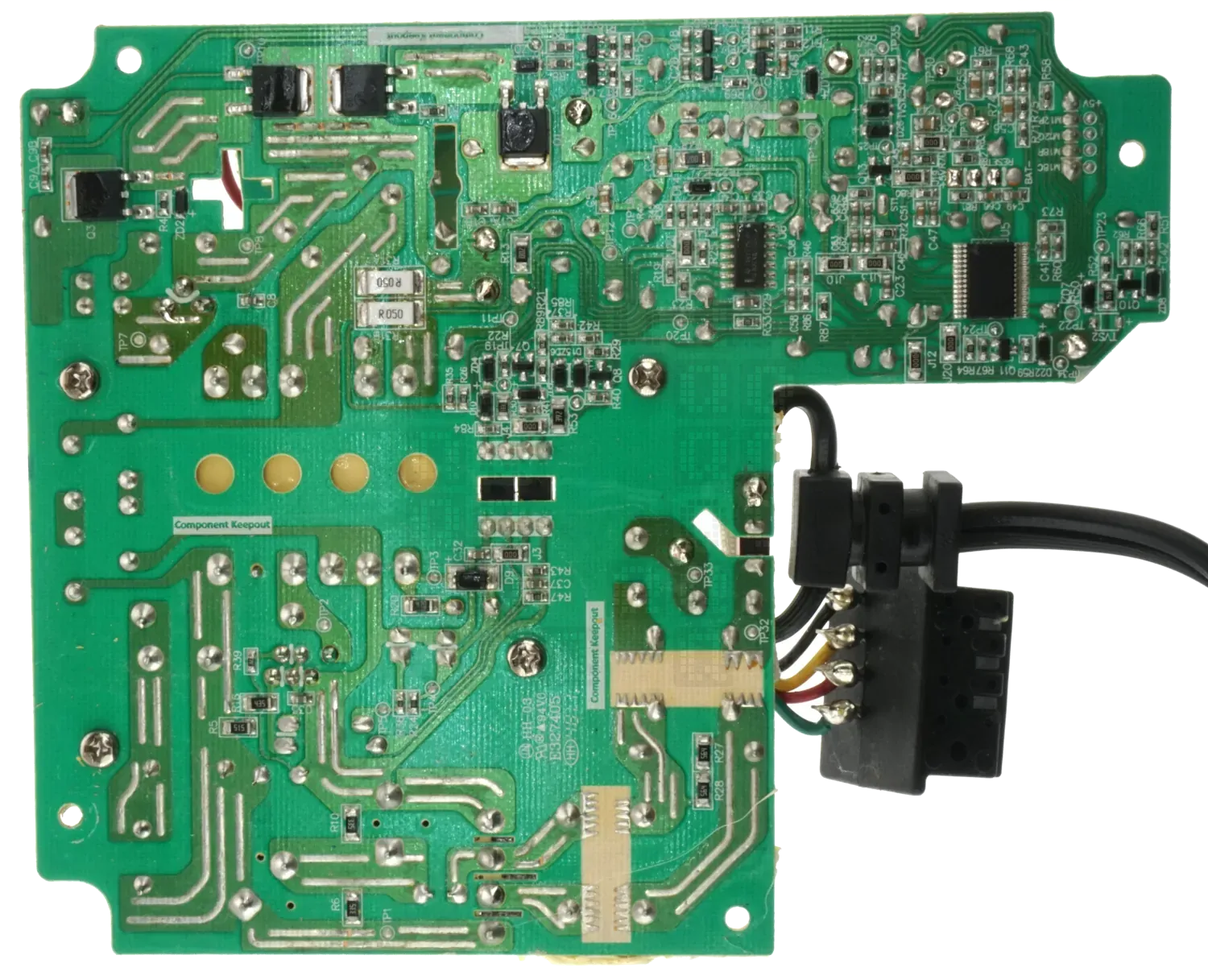
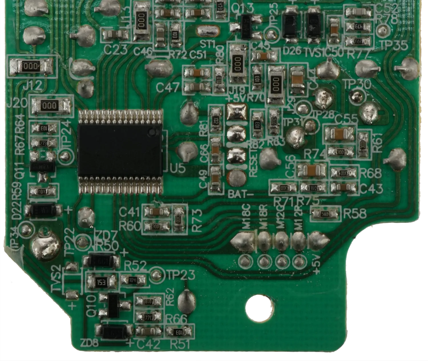
And this is the bottom of the circuit board. My apologies for the slight blurriness; my camera was having issues with the reflective solder joints and couldn't quite figure out the focus. I have other higher-resolution photos of smaller sections of the board which I will share at a later date. U5, the brains of the board, appears to be a R5F100AC4 16-Bit Microcontroller. Half the circuit board seems to be dedicated to power supply and power regulator components. I might look at this more later, but most of it appears to be pretty standard power supply design. Though I must admit I haven't seen the sawtooth solder pattern on keep-out zones before... If someone knows the purpose, I'd be interested in an explanation. 5-Pin Header has labels on this side, and 4 Pin Header is also labeled on this side - We have BAT-, RESET, and +5V...but the other pin label? That's the same one covered by glue on the top side... Sigh...
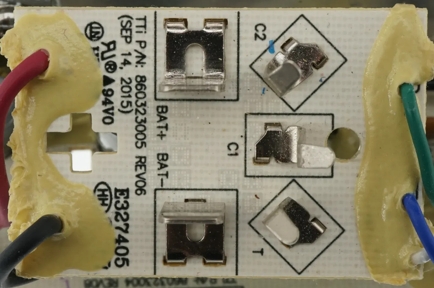
Quick look at the M12 Battery Charger Riser Board. Not much to see from this side. It is labeled 'TTi P/N 860323005 Revision 06 (September 14, 2015)'
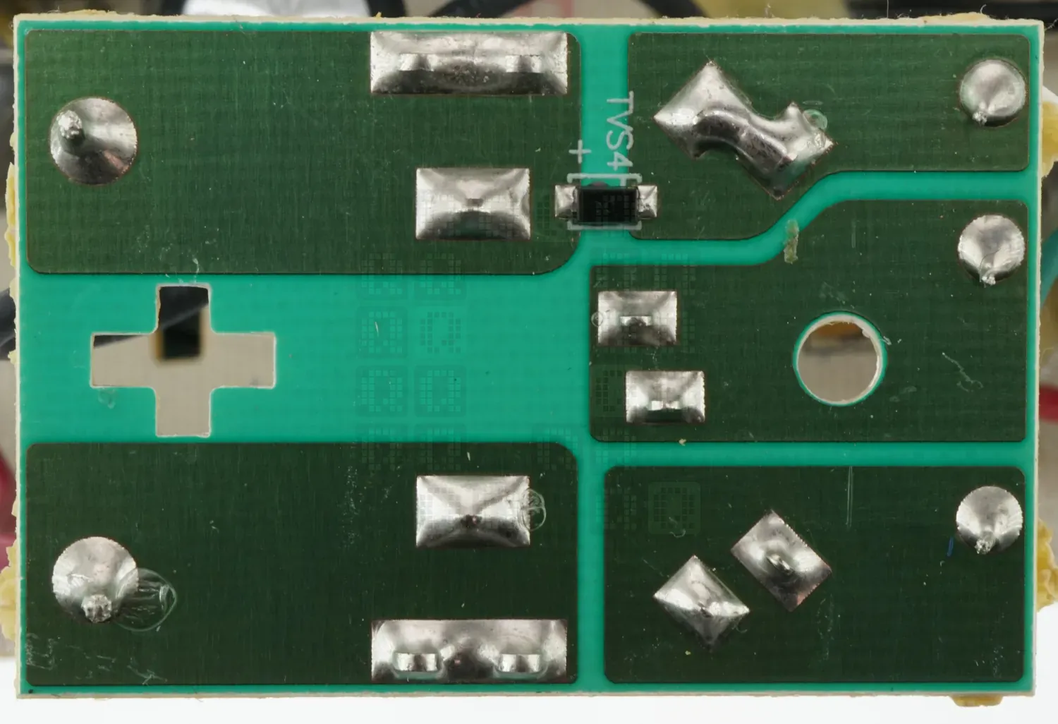
Bottom side of the same board... Even less to see here - only thing we have is a surge suppression diode.
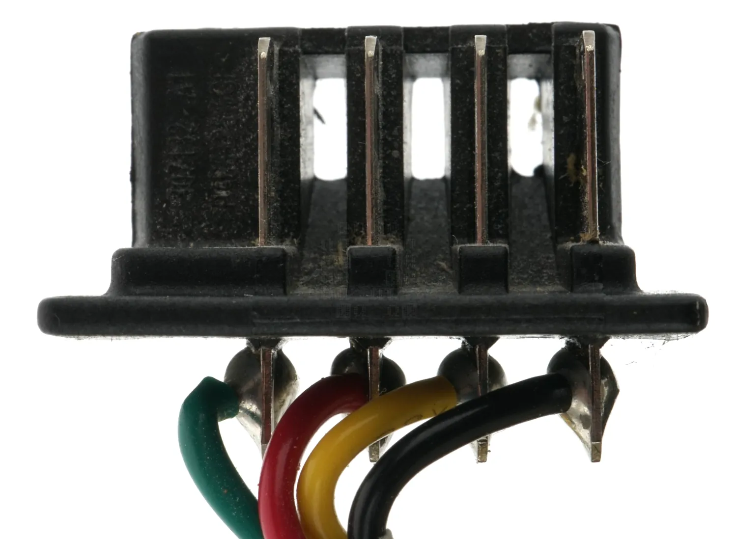
A quick look at the M18 Battery Charger Connector. Right to Left we have:
Black Wire - Pack Negative
Yellow Wire - Communication
Red Wire - Charge Wire (Battery connects internally to Pack Positive)
Green Wire - Communication
Empty Spot where Pack Positive connection would normally be.
Here is a closer view of the MCU portion of the circuit board. Nice and clear too...Might not be good enough to trace everything, but it'll be a decent start.

