2022-11-02 (or thereabouts)
the saga of the un-obtainium Sinpacs continues in this teardown and reverse engineering of the next Sinpac; a CV25-165 of more recent origins; This is also one that was new and appeared to be working properly.
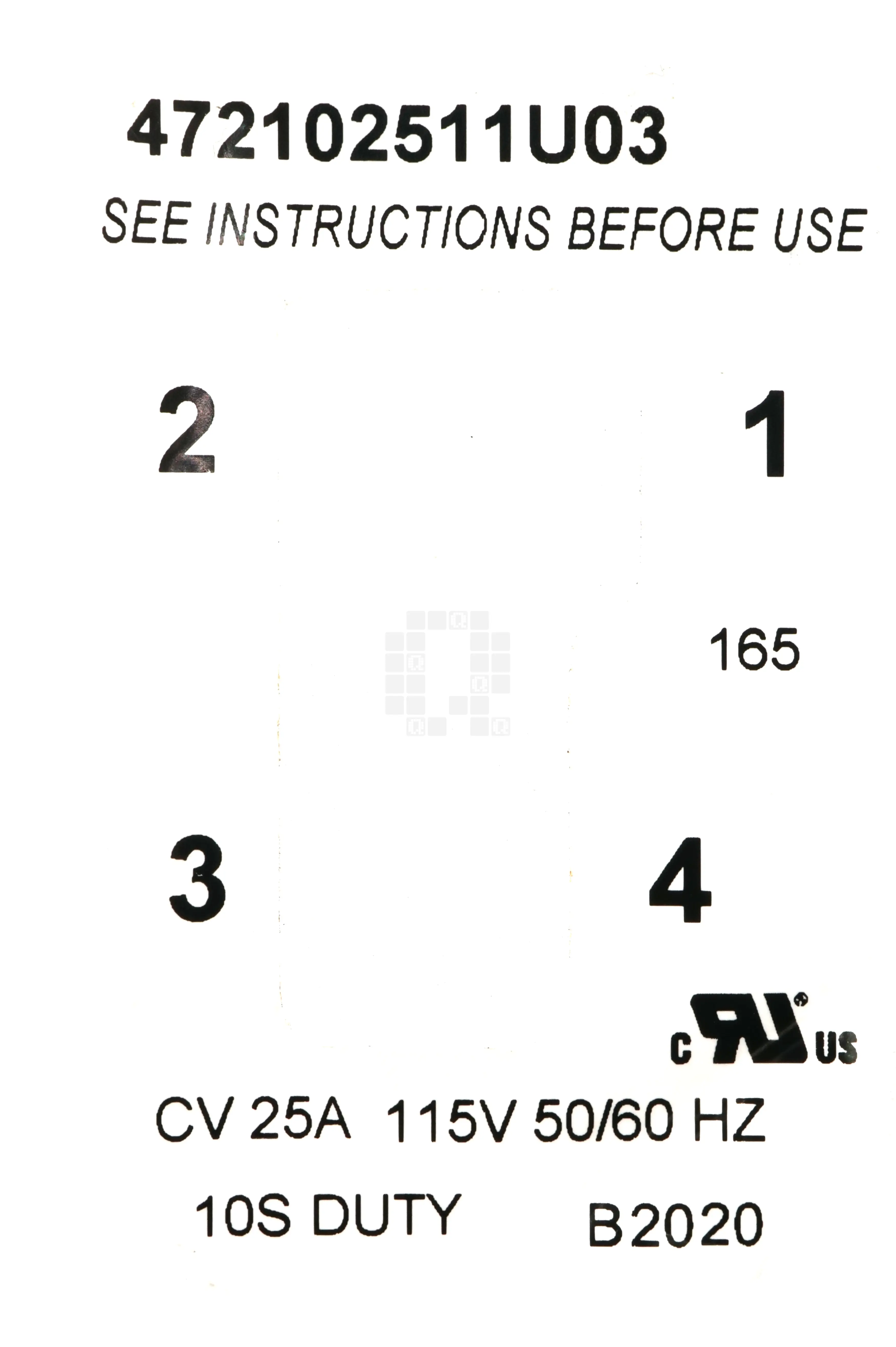
We'll start with what remains of the label off of the unit. 472102511U03 (Click for information about this number- PDF) CV 25A 115V 50/60Hz [Input]10S[econd] Duty B2020 [Date code] 165 [V Dropout] Surprisingly, this unit was fairly easy to remove the epoxy from. It helped that the circuit board was coated in a thin layer of silicone.
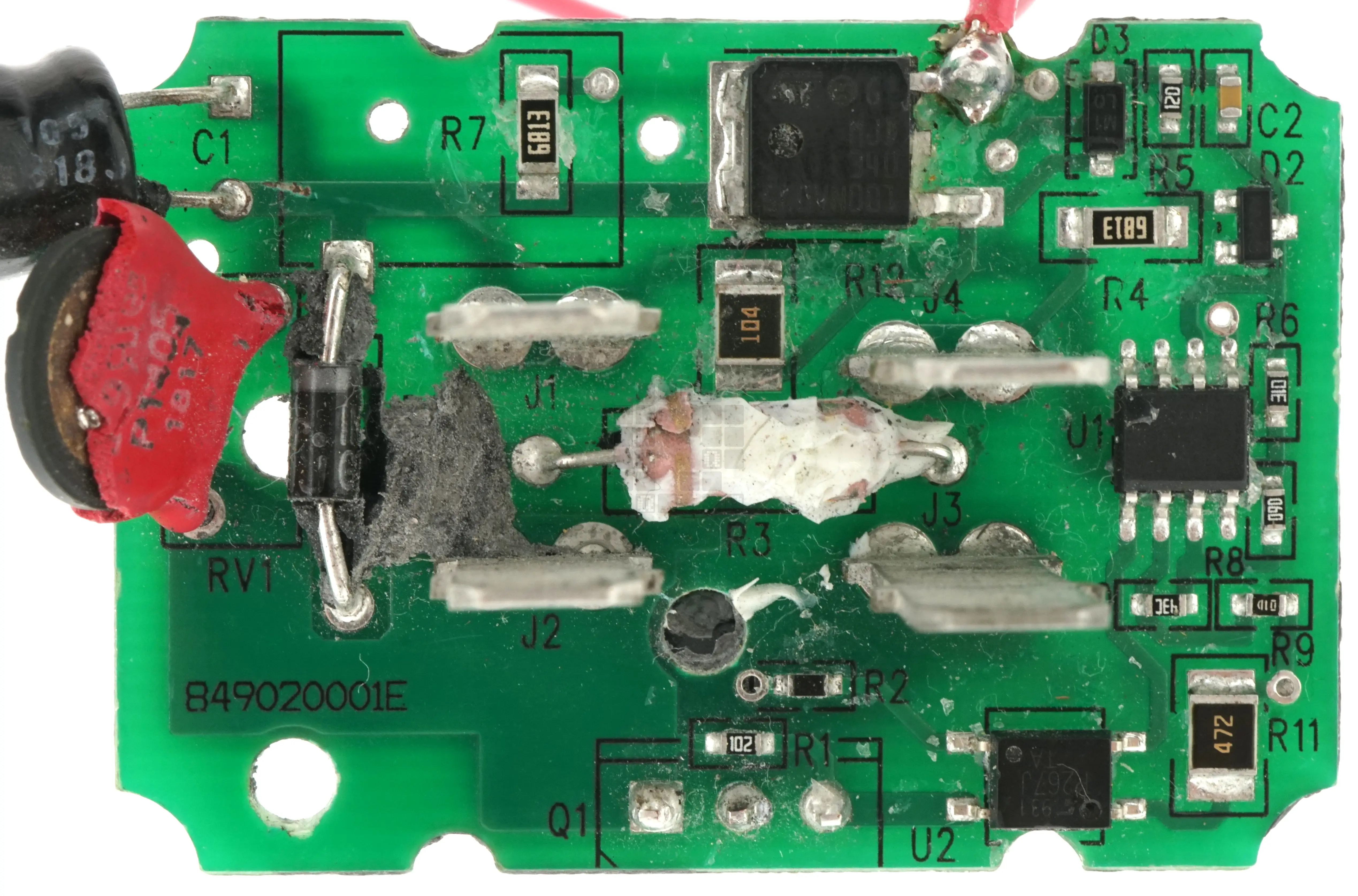
Our first peek at the board. The TRIAC (Q1 and its copper heatsink) has already been removed. Note sure what 849020001E references...
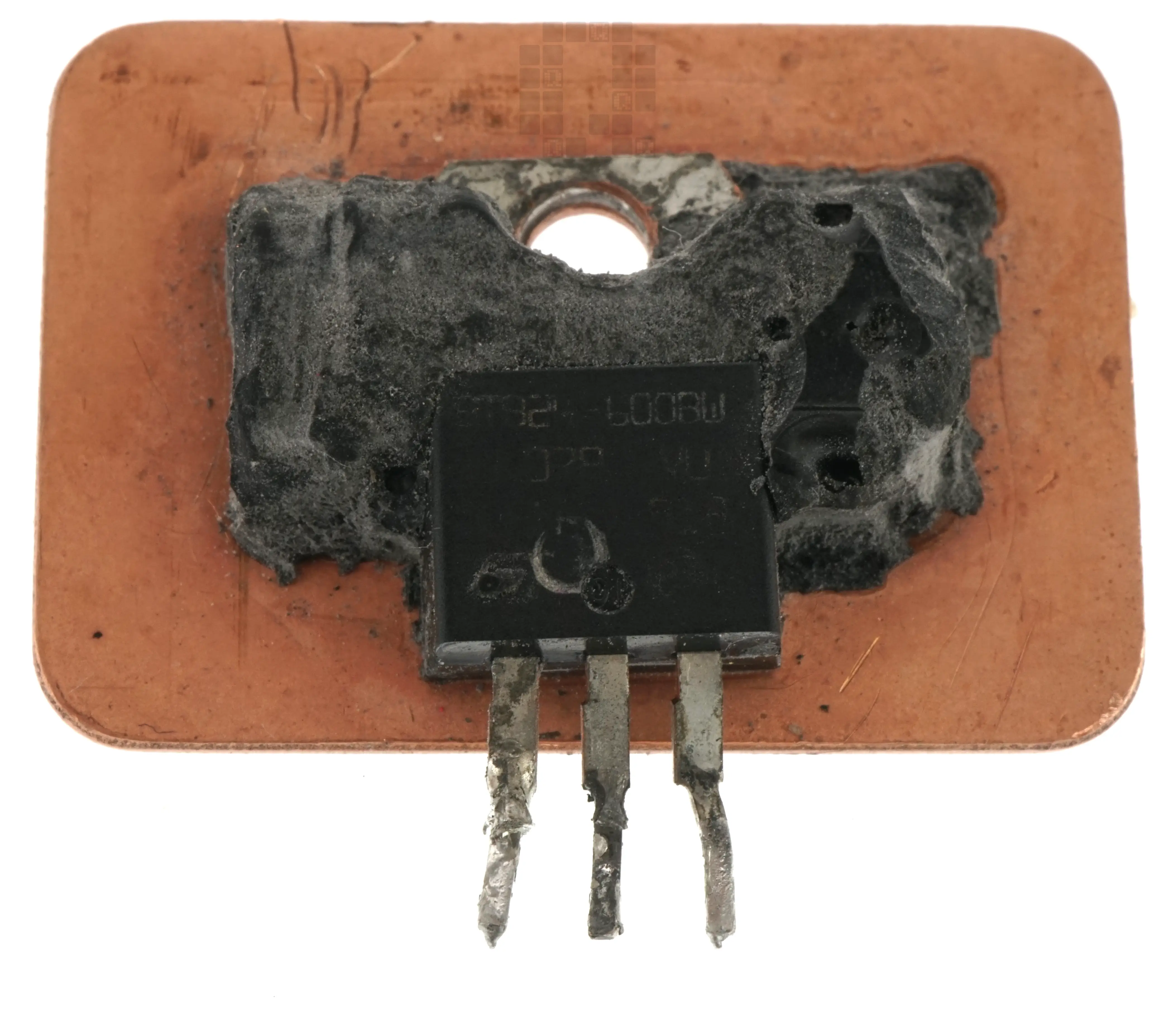
BTA24-600BW and copper heatsink
Top of the board with all through hole parts removed. It's starting to look nice and simple.
U1: LM393
U2: P267J Optoisolator
Q2: MJD340
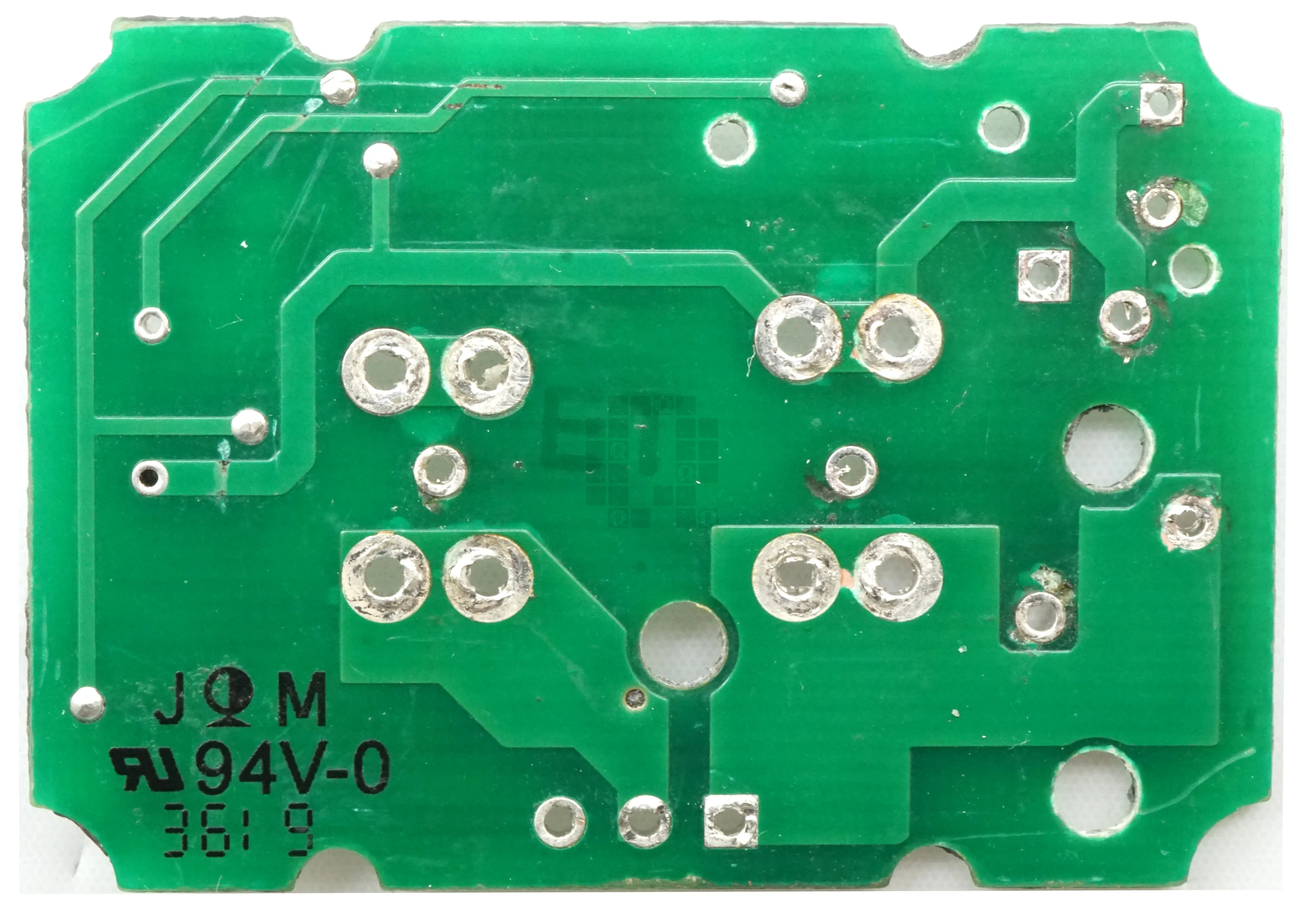
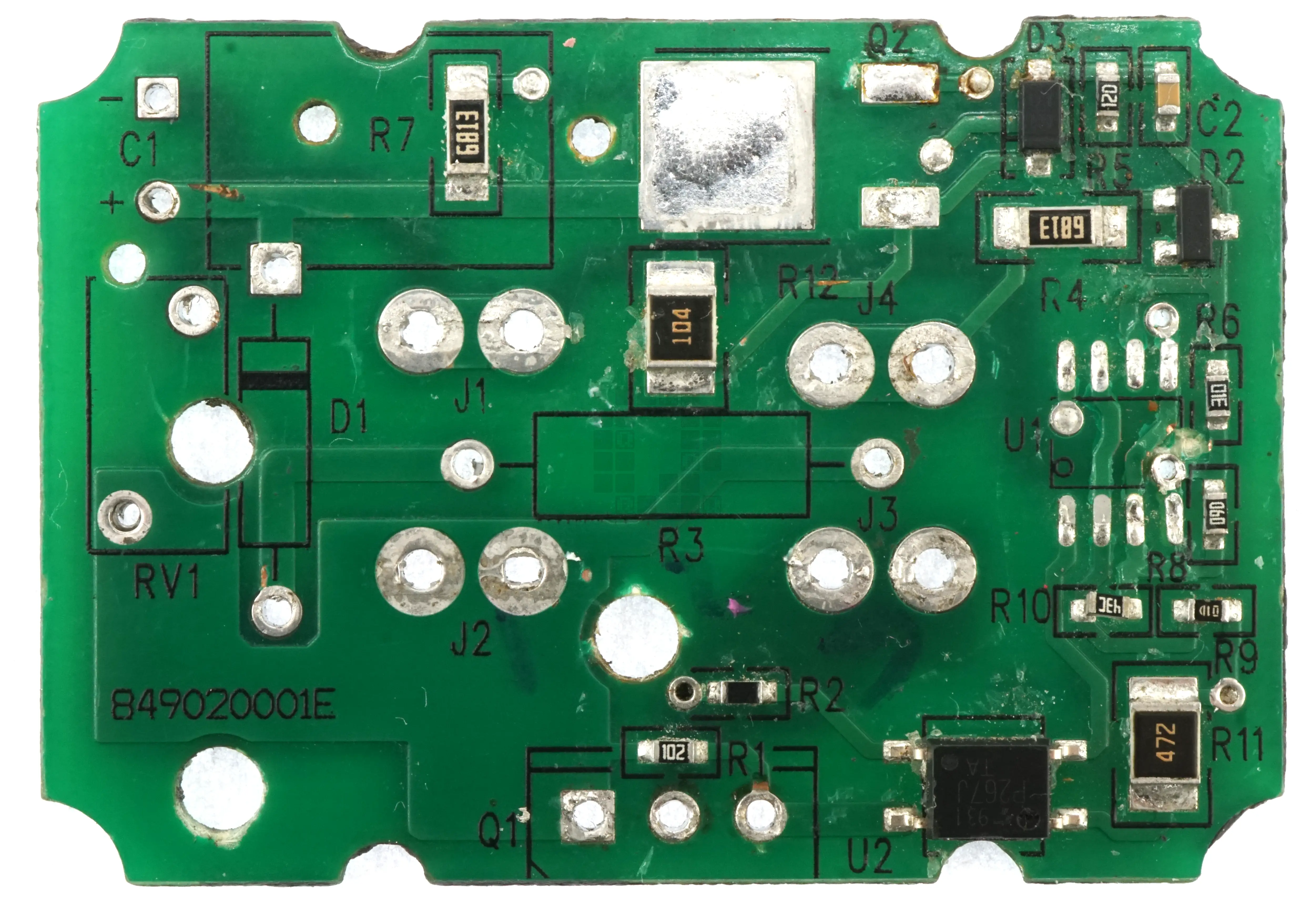
Bottom of circuit board.
And a final view of the top of the circuit board with U1 and Q2 removed.
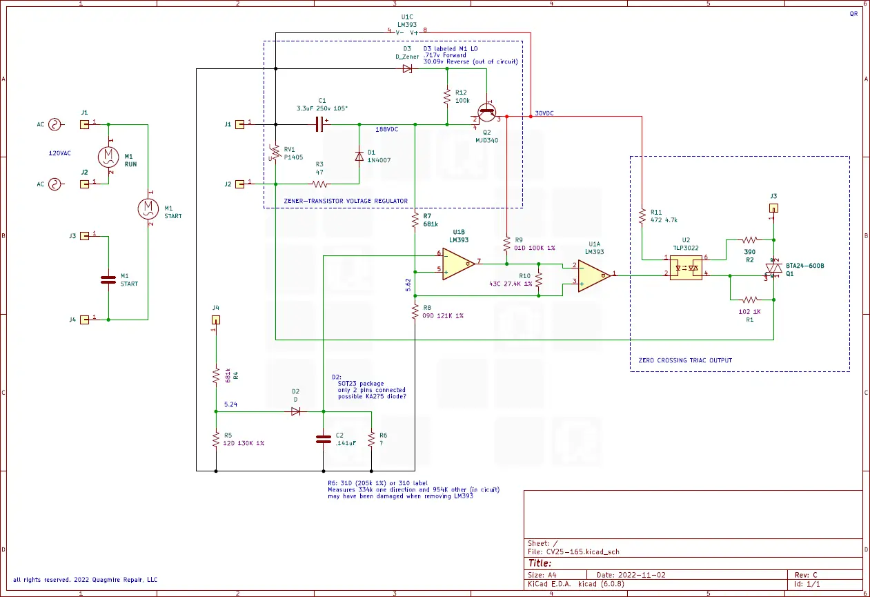
and here's my best guess on the electrical diagram. There's a couple unknowns (diodes and one resistor). I'd really like a positive identification on the D3 and D2 diodes.
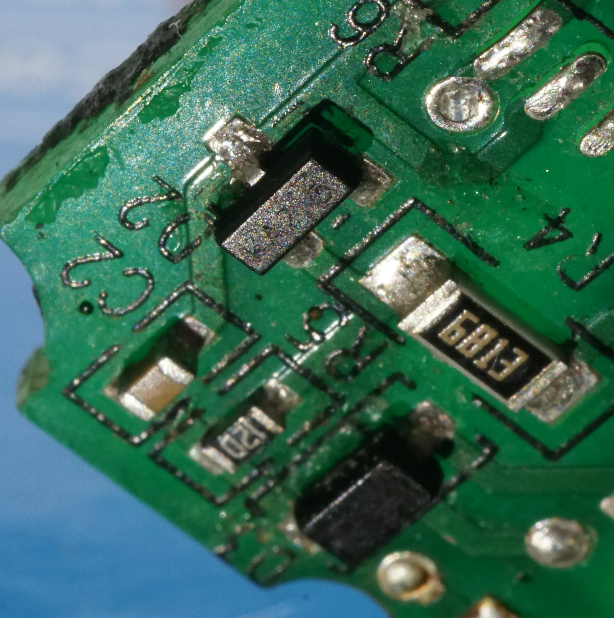
Closeup view of D2 - marked KA2 - possible BAS16 from DIODES INC? (PDF, 5 Pages, 573kb)
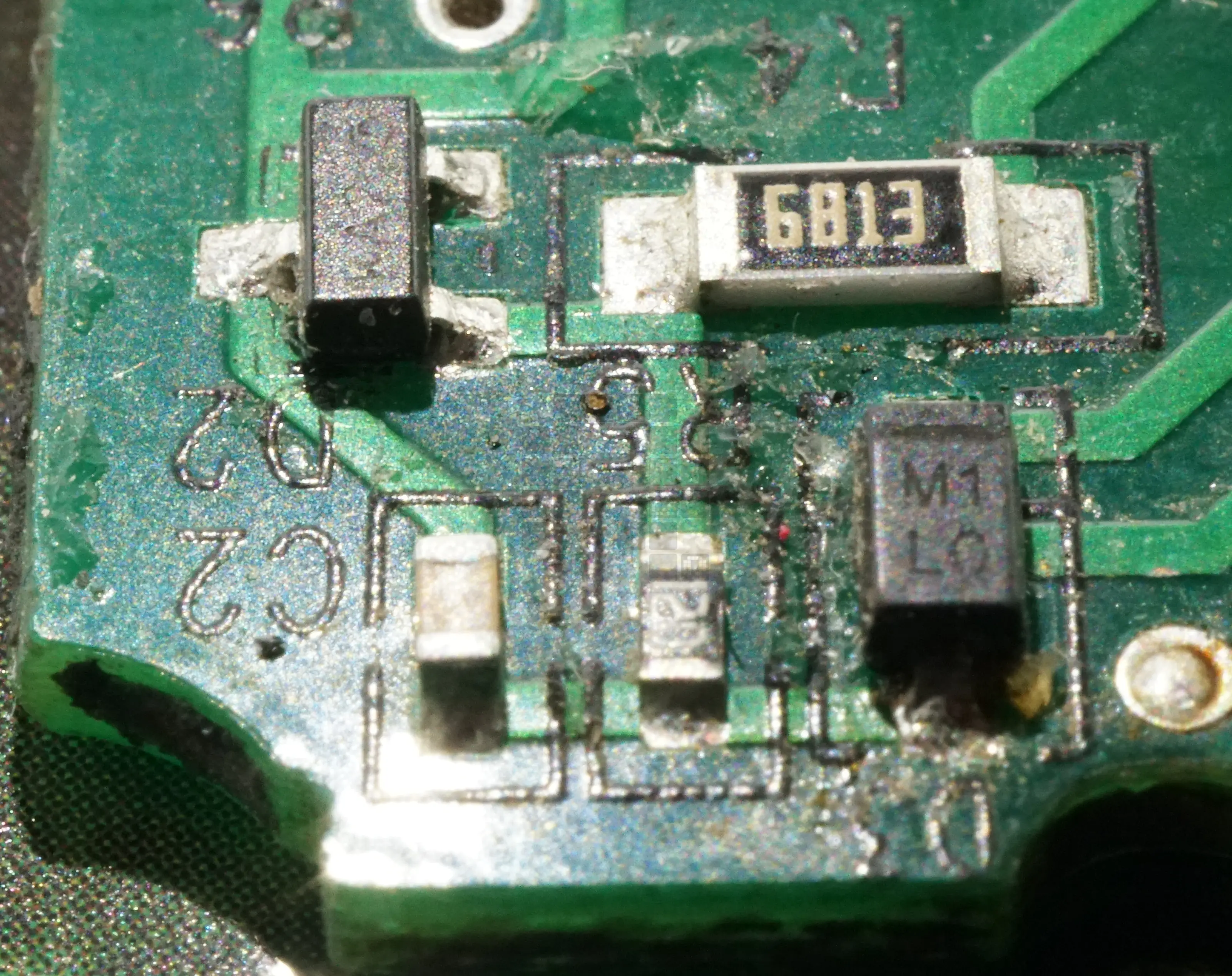
Closeup view of D3 - marked M1 - possible MMSZ5256B 30V zener diode from DIODES INC? (PDF, 5 Pages, 370kb) Date code doesn't seem to work though...
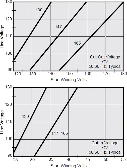
Here are the line voltage charts for these parts that explain what voltages are expected on pin 4 (J4) and the expected output of the second op-amp. Quote from DATASHEET (PDF, 2 Pages, 202kb) below:
"Induced voltage across the start winding is directly proportional to motor speed and line voltage. All SINPAC Switches use this voltage to switch the start capacitor out of the circuit. Your motor with a SINPAC Switch must generate a voltage that is 20% greater than the switch cut out voltage to assure cut out of the start capacitor. Refer to charts below."
If you or someone you know finds this info useful and decides to start building something similar, please let us know. We'd like a royalty check and the option to buy some of your devices. ;)
Note: All electrical diagrams are believed to be correct as far as we're aware; however, there may be mistakes and omissions. You assume any and all risks by using these diagrams for anything other than a pretty picture to look at.
Part 1 of the un-obtainium saga: the CV40-165
Part 3 of the un-obtainium saga: the CV50-165
Part 4 of the un-obtainium saga: Alternatives - SAMUSCO ECS224L

