
Please Note: Clicking on an image will take you to a higher resolution version of the image you clicked on.
2026-08-25: Today we're going to look at an AKG DMS300 PT300 Bodypack for the last time before it gets scrapped. You'll understand in a little... Background story or teardown first?
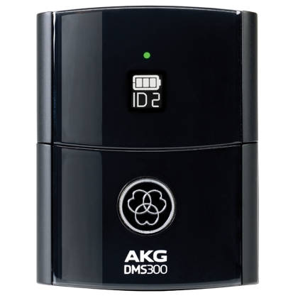
Promo shot by the manufacturer.
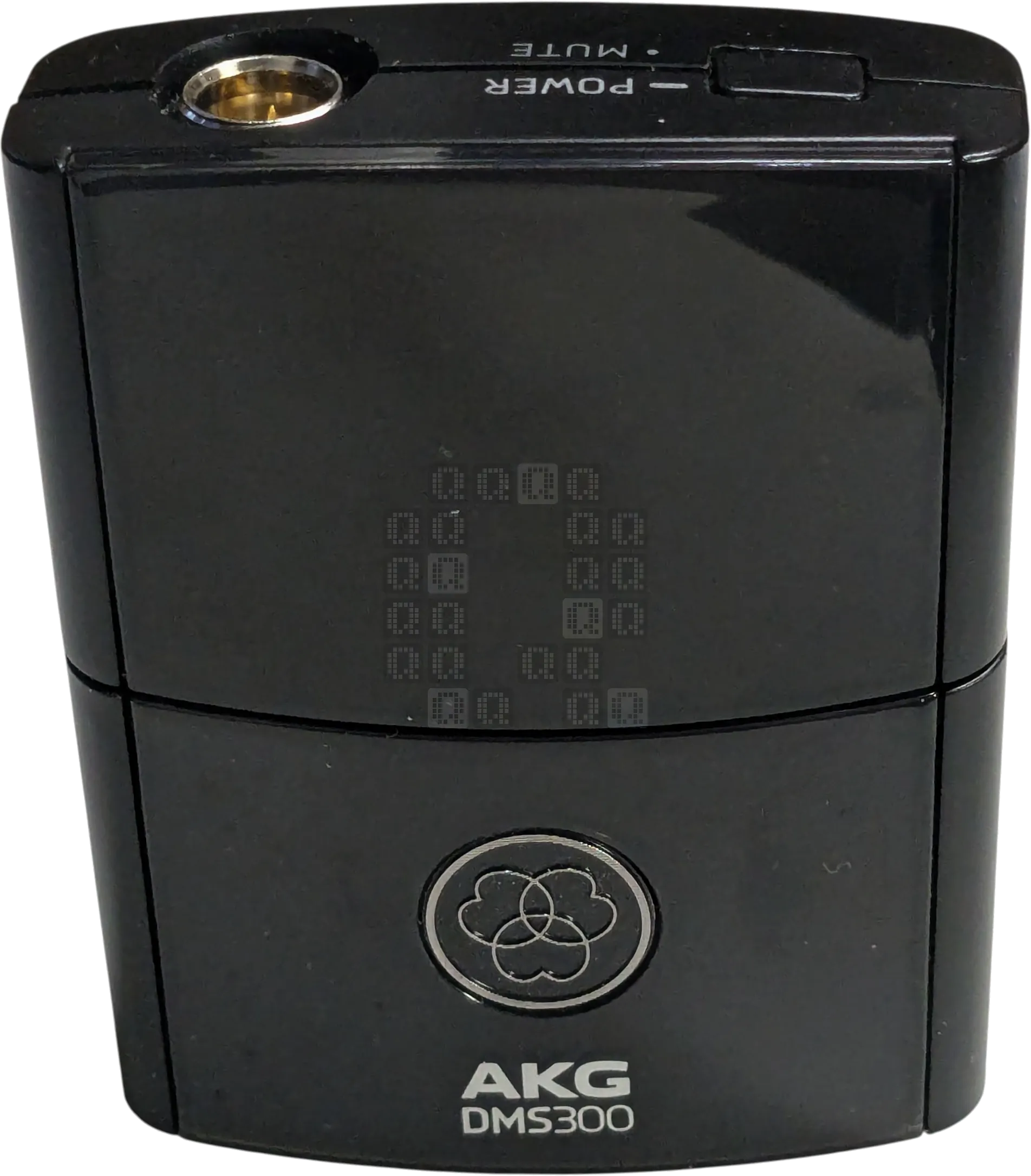
Image of the front of the bodypack.
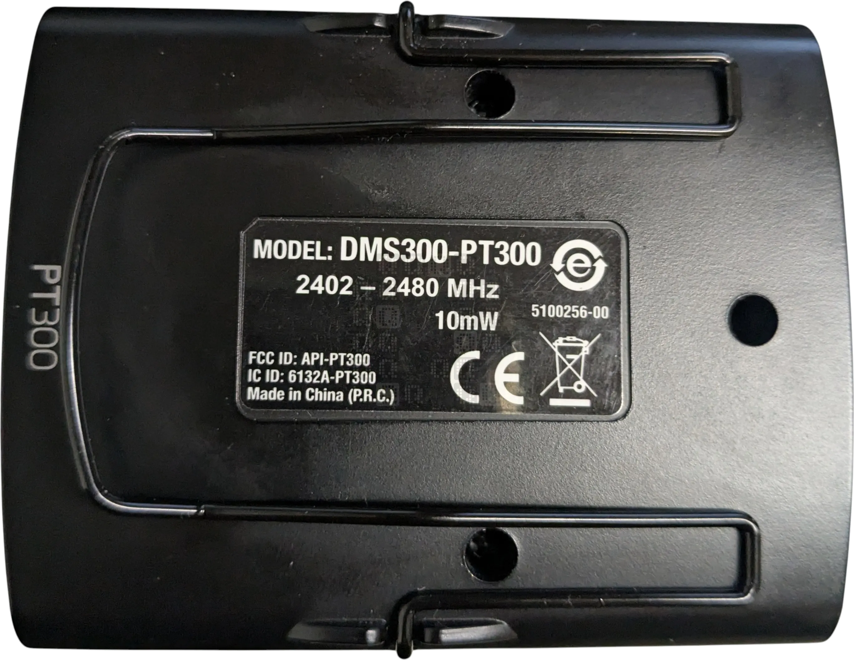
Image of the label on the back of the bodypack. Notice the 10mW power rating...we'll come back to that later. There's also an FCC ID: API-PT300 and a frequency range of 2402-2480MHz. 3 phillips screws & the microphone jack nut hold this unit together. Belt clip clips into the sides of the unit.
So, the story: This is a tale of a situation where nearly everything goes wrong on a repair; but along the way I learn some things. Hopefully you do too. (and please don't buy this product!)
- Story -
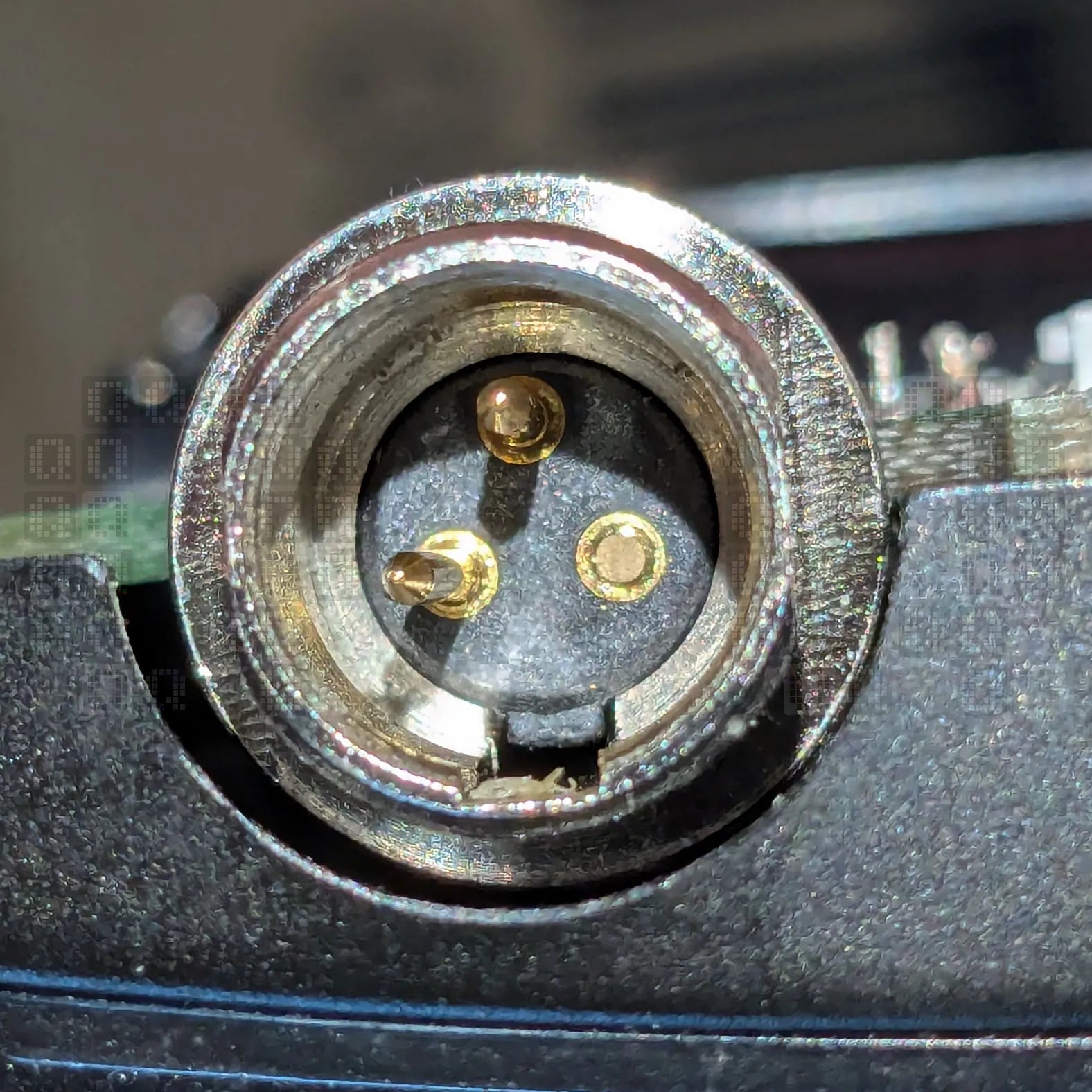
This is the problem that started the saga. But the complaints of microphone audio failures - crackling and audio dropouts - go back way before this point. This is simply the point where I offered my assistance. This jack is supposed to have 3 pins, not two and I can replace that - most jacks are fairly easy to replace... except when there is a poor design surrounding an easy-to-replace jack.
It didn't really come apart the way I expected. The back housing has a plastic ring around the microphone jack. (this images is taken with the circuit board lying in the front housing with the jack removed from this ring.) But the wires to the battery are soldered to contacts on the front housing and are really short. Not to mention the circuit board standoffs go through the circuit board (probably what you want to support the audio jack and top button, but...) It is snug and every movement puts stress on the microphone jack's connections to the circuit board. (not what you want to do after a repair)
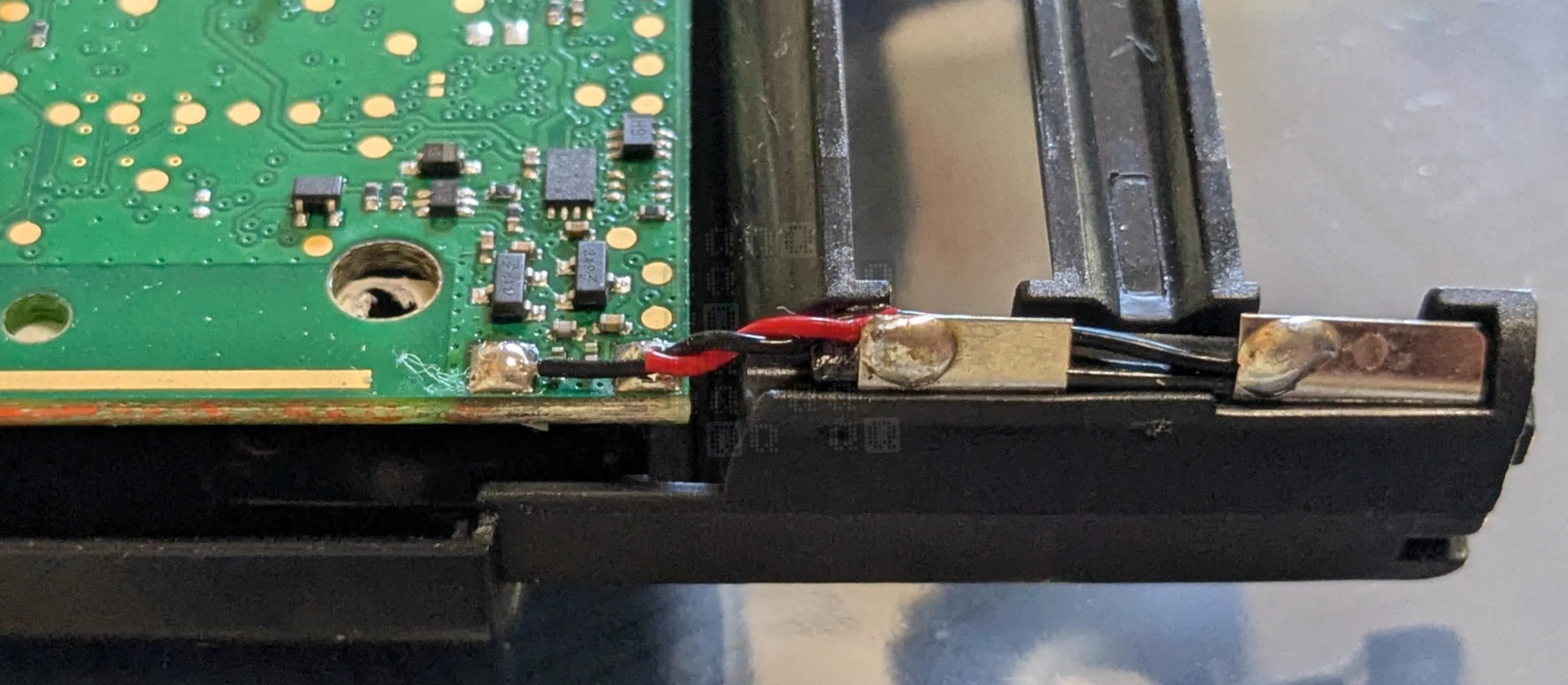
(You did make note of which battery wire goes where just in case you accidentally break both off right? One is a little longer than the other and the board is not labeled. Here you go, just in case!)
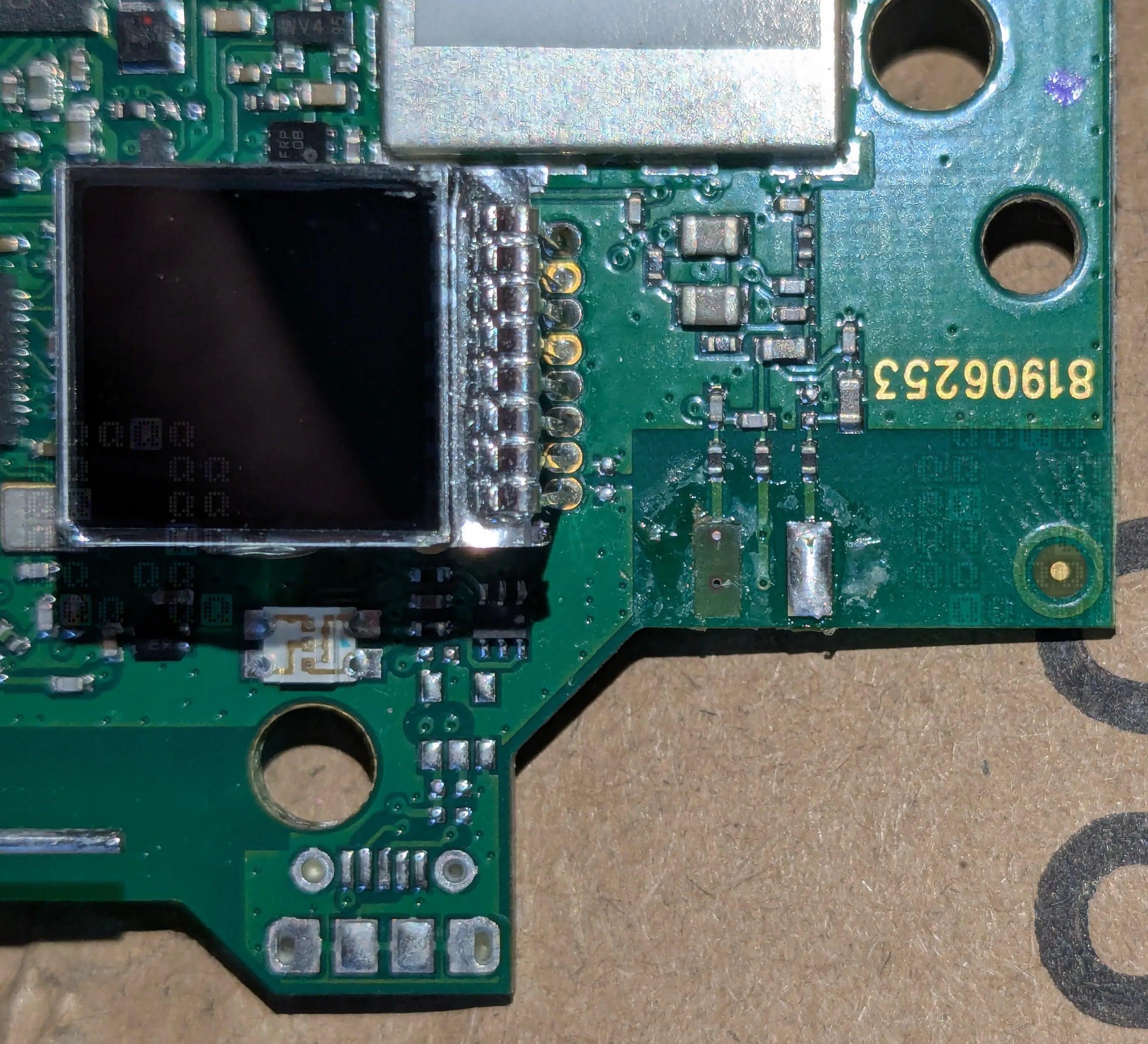
I decided my best bet was to clip the jack pins off and then desolder each pin separately to avoid any damage. Unfortunately there was no need to clip one pin - it came away from the circuit board, pad and all. Just for reference, those little ?resistors/inductors? right above the pads are 4020 - that is 0.040 inches by 0.020 inches. That makes the trace I need to connect to somewhere around 0.015 inches. There are test pads on the back side of the circuit board, but unfortunately they connect to the vias under the pad that lifted. I really need to ask who designed this... This will be the point of failure for almost every single one of these units.
It was at this point that I did not take many photos - I was concentrating on fixing it and not documentation. I did a decent soldering job, verified everything was connected properly and then epoxied everything in place to prevent future issues after assembling it in the back cover. I was a little worried about it after the pad lifted with the pin, but it turned out ok... (I thought - foreshadowing) If you need a replacement jack for this unit, you can buy either the IO-TXLR3-M-PS (Digikey link) or IO-TXLR3-M-PV (Digikey link). The difference is the pin type - Solder cup (PS) or solid pin (PV). A jack with wires soldered between the jack and the circuit board would make a lot more sense here. If you want to fix one of these, grab the solder cup jack, then solder wires to the jack, bend the pins 90 degrees and heat shrink them. Then solder the wires to the circuit board. Stress point eliminated. Unfortunately I did not think of this in time for this repair.
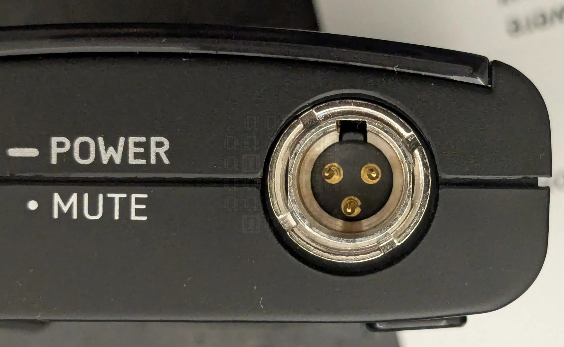
No, those pins are not straight and this is not fisheye on the camera. One week and one use later it was back again with some bent pins and a complaint about the mic crackling while moving around. (I didn't send it out like this.)
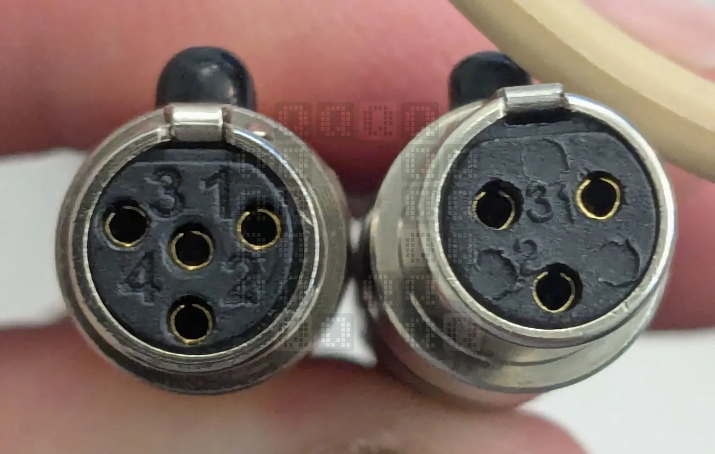
A couple questions and a retrival of a mic answered some questions. On the left is the 4-pin mini XLR connector that was being inserted into the 3-pin mini XLR jack. The spec for the 4-pin mini XLR says it is made specifically to not fit in the 3-pin mini XLR jack. We now have a root cause for the issues. Extra force was being applied to make the plug latch in the jack (which was physically impossible) Unfortunately, the pins on the jack have been broken off the circuit board again. (continuity is intermittent) I'm not attempting another repair on it.
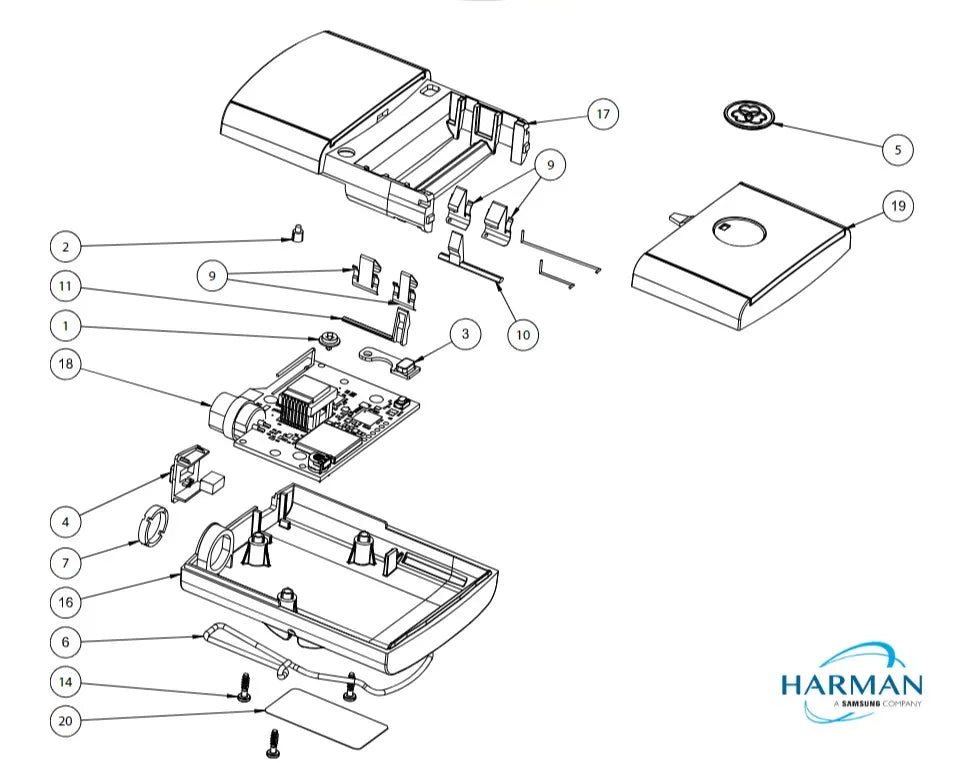
This is the parts diagram for the PT300 supplied by Harmon. #18 on the diagram is 5096874-00 PCB Assembly. Costs roughly $140. Did I mention that the unit was also dropped and the battery cover tab broke? #19 is 5109408-00 Battery Compartment Mechanical Assembly. (About $9) #5 is 5094926-00 Cardiod logo is $6. At this point, you're over halfway to the cost of a new unit. Hmm.
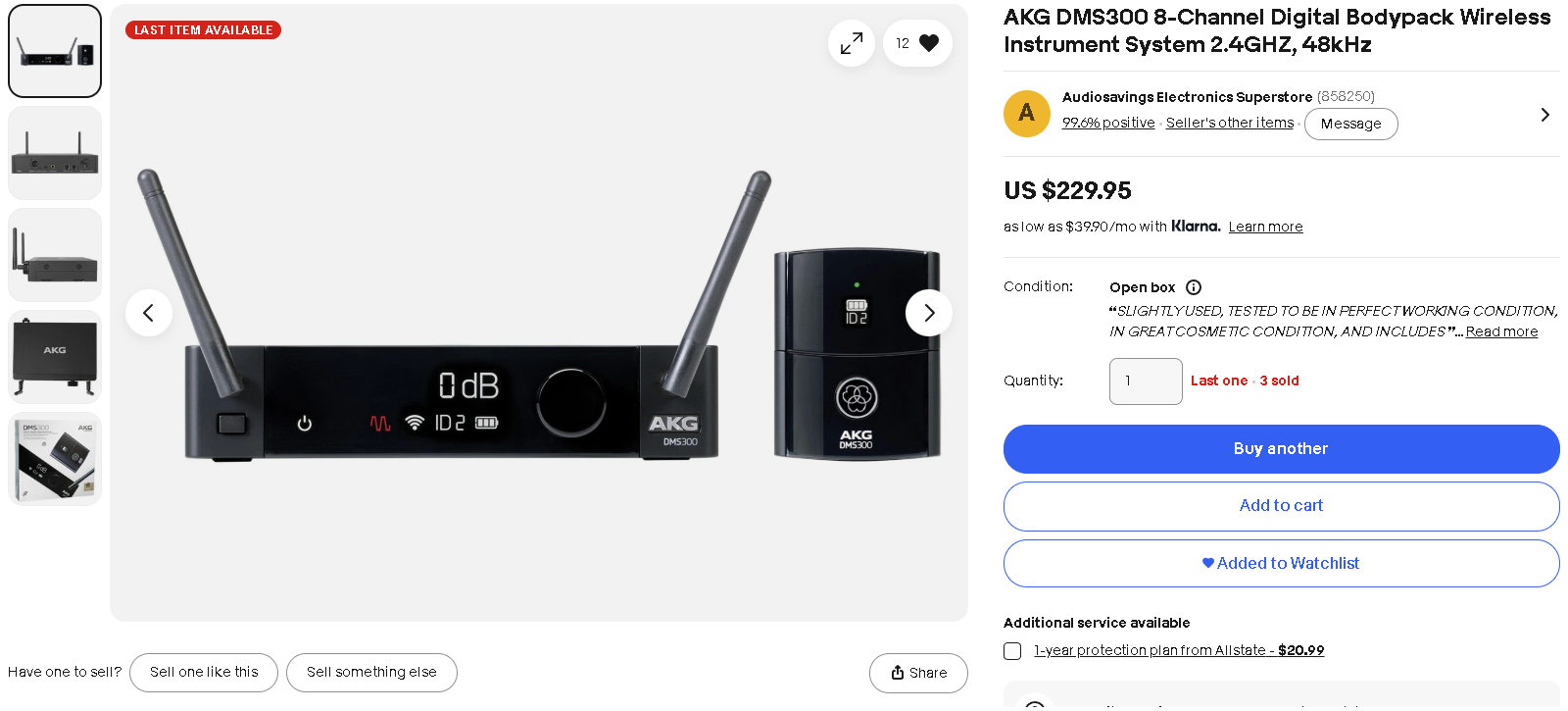
Open box DMS300 system on eBay is[/was] $229 shipped. We're going this route now. It arrived brand new with a sealed box. (Postscript: This replacement unit worked fine for a couple months, then also developed issues with a broken jack connection to the circuit board.)
We have now reached the end of the story. You now know how we got here. On to the teardown!
- Teardown -
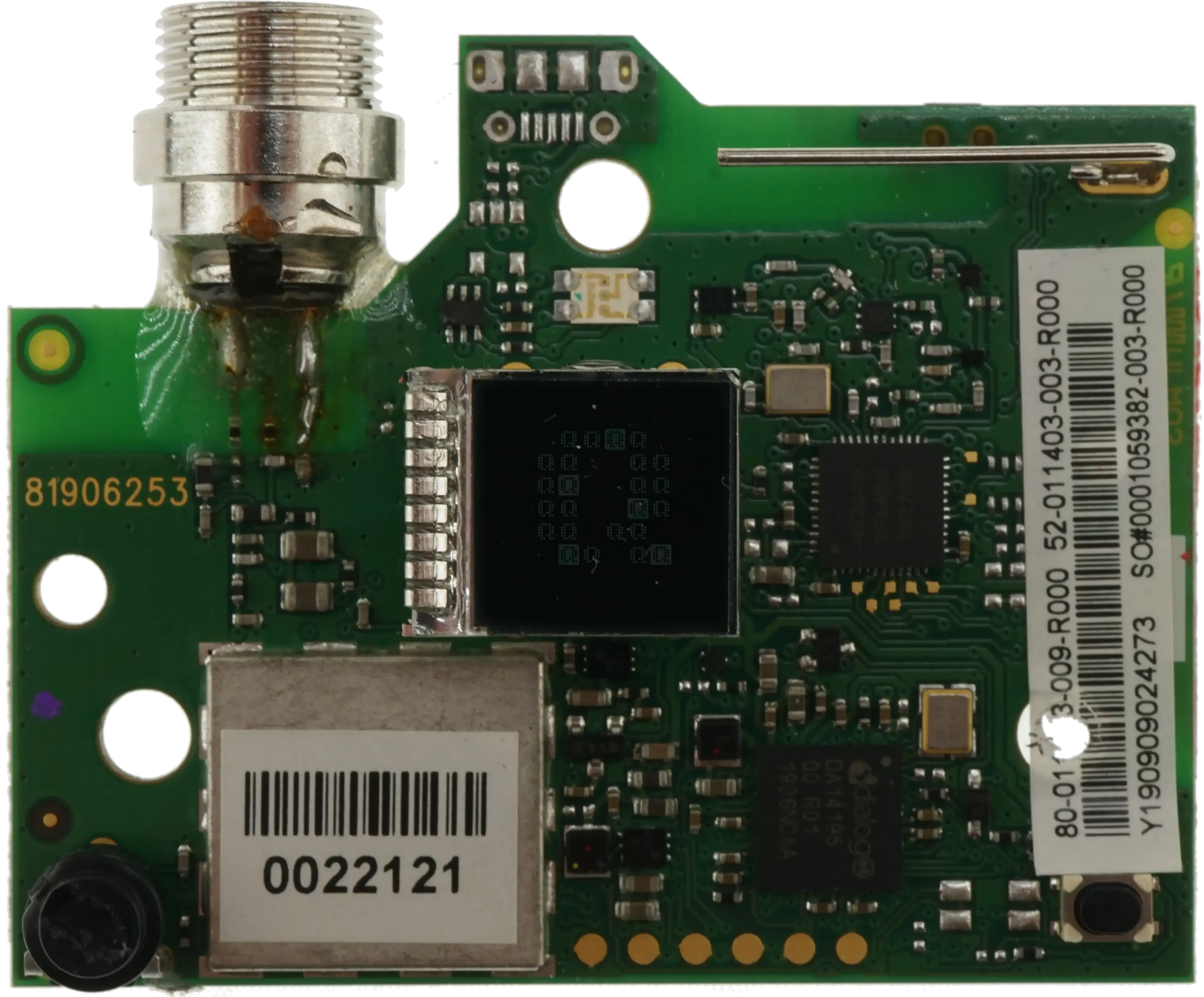
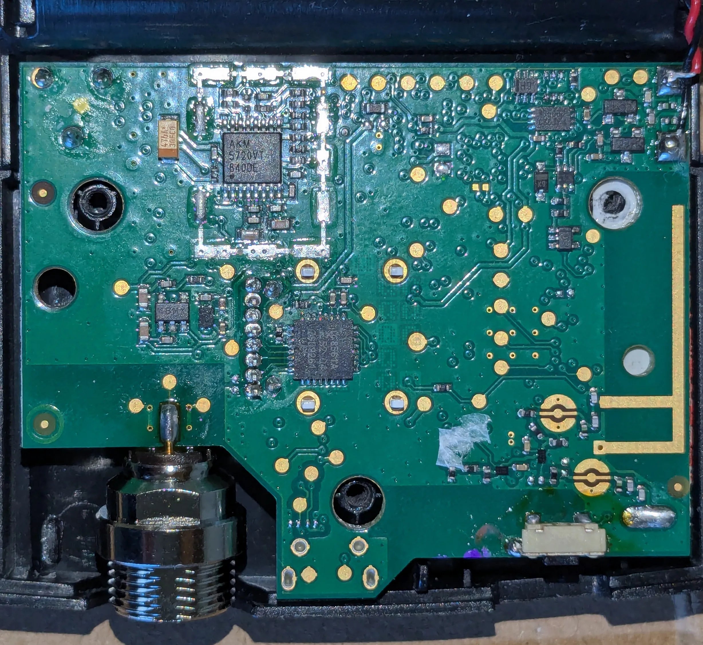
Front of the circuit board. Since this is a transmitter, we're going to start at the microphone jack and work our way counterclockwise through the circuitry towards the antennas. (You can see my repair to the jack in this photo and the next; I do not suggest repairing it this way - see story above.)
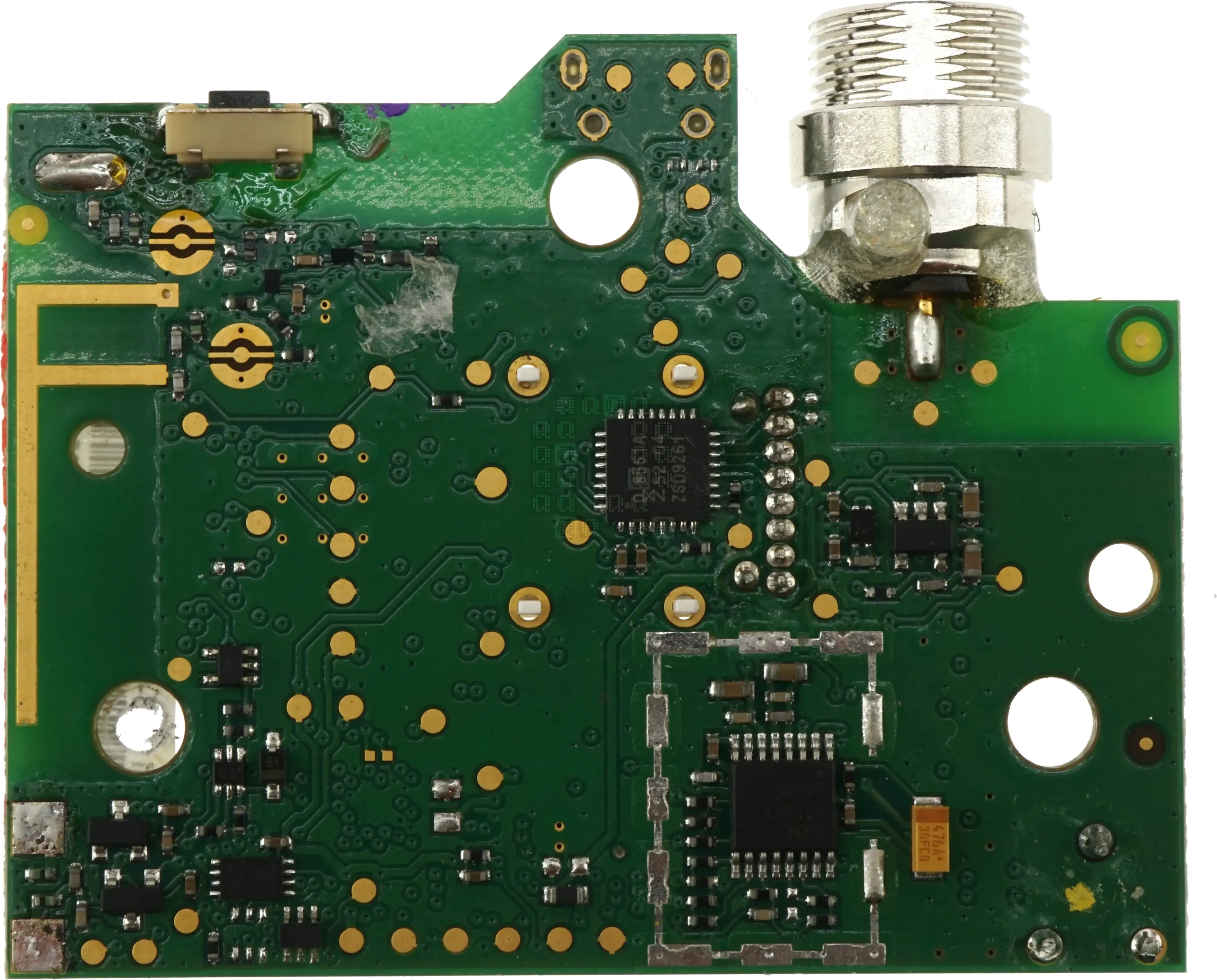
Back of the circuit board (I'll be going clockwise from this view.)
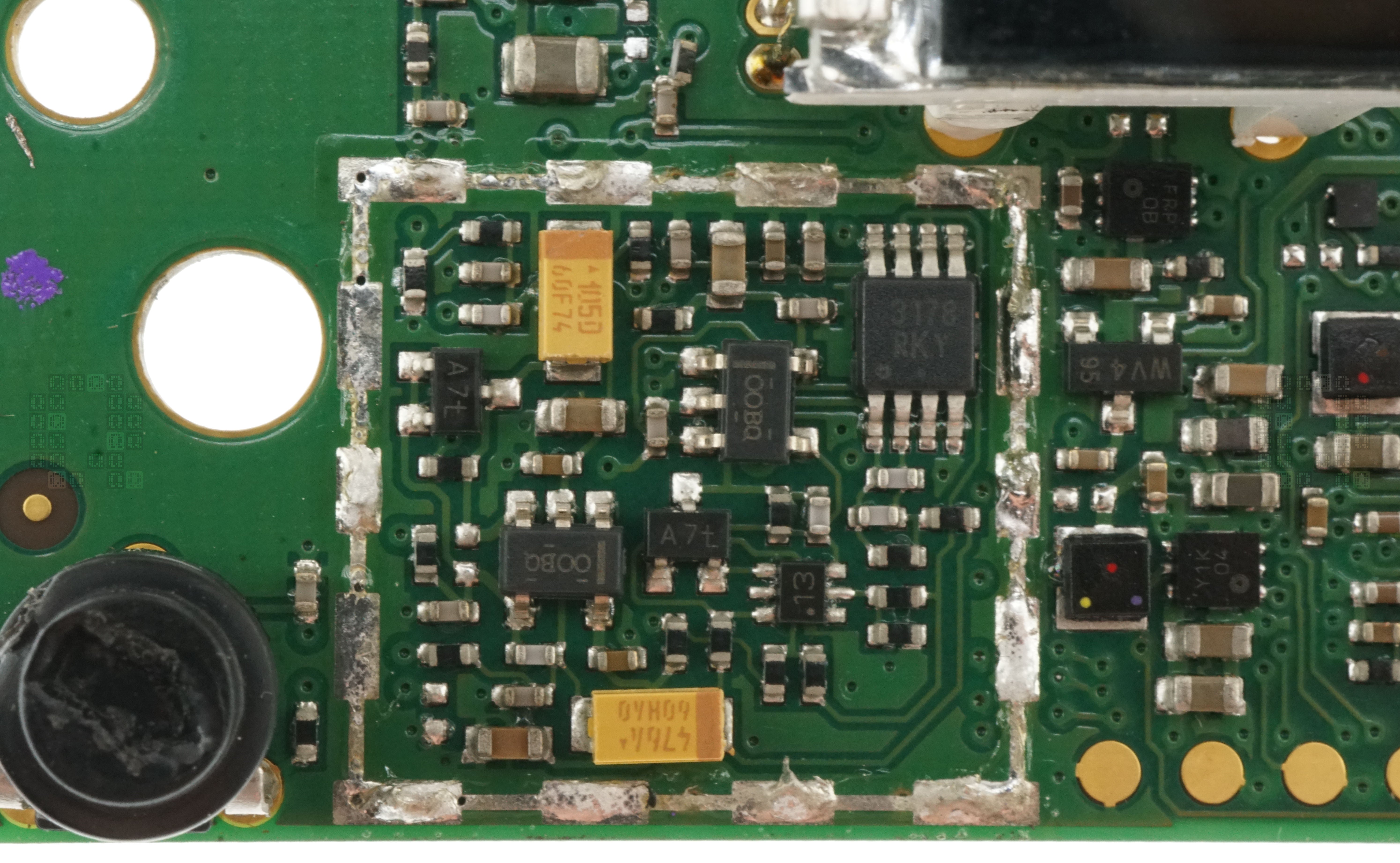
This is the first step in the journey. This step was covered up with a metal cover which I have removed. Unfortunately I have had zero success identifying anything in this step. Yes, I know there are transistors (A7L), 2 tantalum capacitors & resistors... but the other 5,6 & 8 pin devices? I'm either looking at a preamp/filter stage or some sort of circuit to provide power to the mic. There is a gain knob in the lower left corner if that helps, but the trace quickly ends up inside the circuit board somewhere.
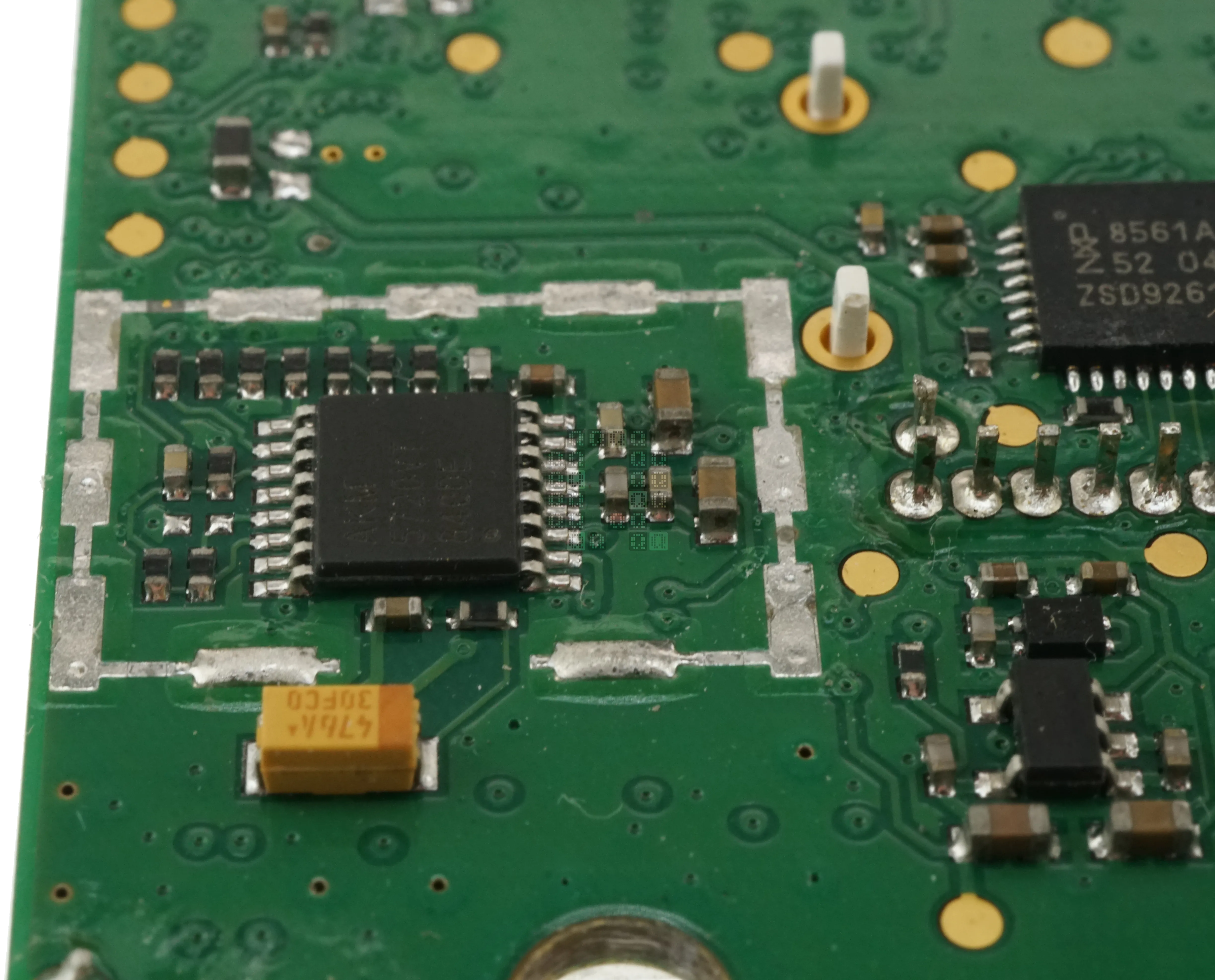
The second step is an AK5720 96kHz 24-bit Analog to Digital Converter. Datasheet for the AK5720 (PDF, 816KB) Since this bodypack advertises a 24-bit 48KHz uncompressed audio stream, we're going to assume it is configured for that. We should have a data rate of 1.152Mbits on pin 9 if this is run in mono mode. (It is capable of stereo)

The Renesas Dialog DA14195 Audio Processor is next. 290.304MHz (that is a really specific frequency!) 32-Bit ARM Cortex-M0. Crypto engine support for AES128/256. USB 2.0. 64KB System RAM, but nothing in the datasheet to state what size the on-board storage is. (or if there is any) There are a couple other parts that interface with this IC. There appear to be six pads for programming on the right as well as six identical ones directly on the opposite side of the board. The two 6-pin ICs at the bottom of the image appear to be related to power control. FRP may be a linear voltage regulator (IXYS USP-6C? 3VDC 200mA) Y1K may be a DC-DC Voltage Converter (Torex USP-6C?)
Brochure for the Dialog DA14195 (PDF, 2.04MB)
Short Datasheet for the Dialog DA14195 (PDF, 439KB)
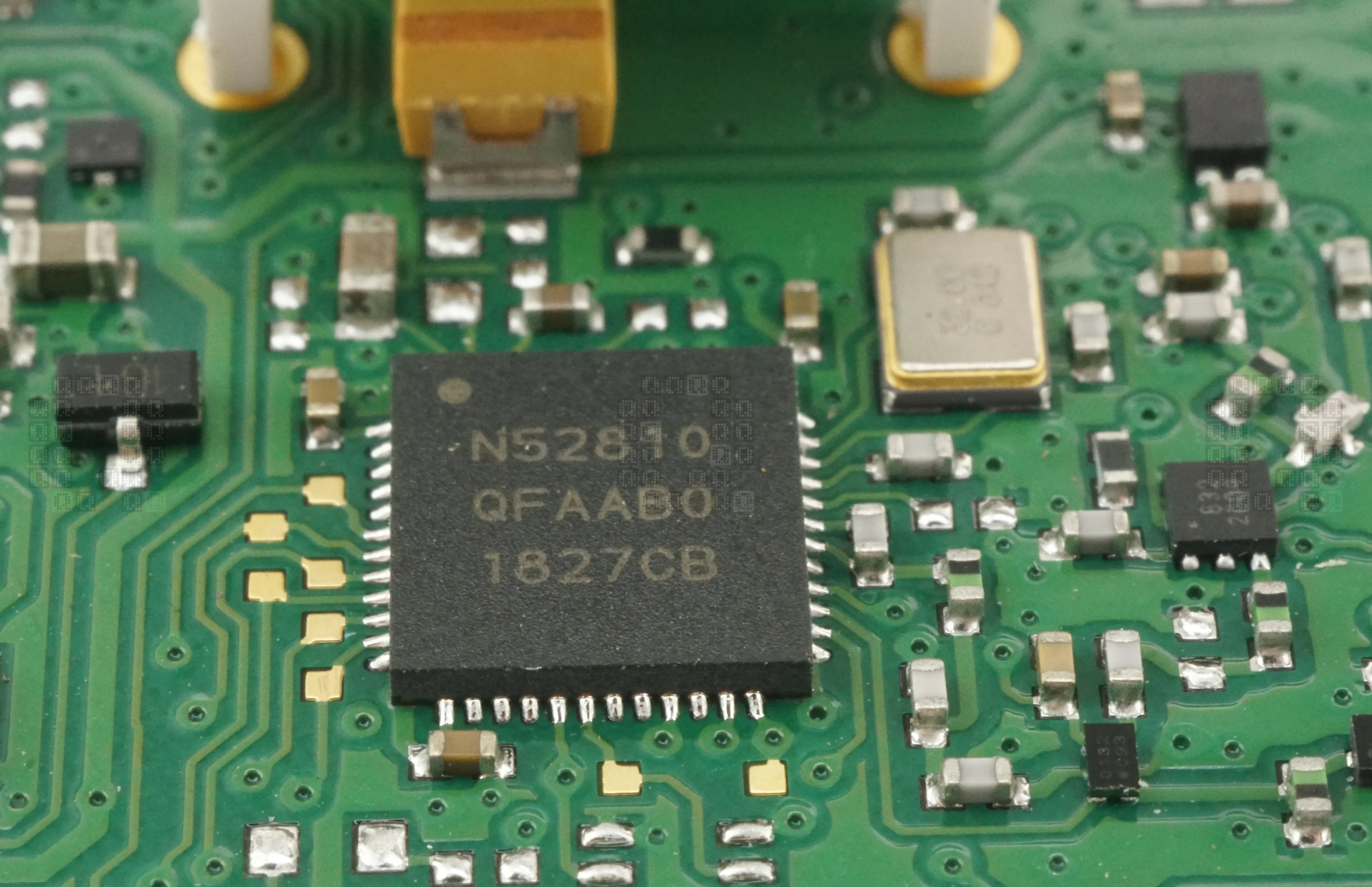
Next is the Nordic N52810 Bluetooth 5 2.4GHz Transceiver with ARM Cortex-M4 32-bit 64MHz Processor. 24kB RAM / 192KB Flash. Supported data rates of 1Mbps or 2Mbps. (guess it is always in 2Mbps with overhead? That will reduce the distance rating a bit.) This device supports AES encryption with EasyDMA. There is only one antenna connection from this IC. Datasheet for the Nordic N52810 (PDF, 6.60MB)
Wait... Bluetooth? I assumed up to this point that this was a WIFI/802.11 type communication device. Datasheet says -20 to 4dBm which converts to 0.01 to 2.5mW. Peak current is 4.6mA (0dBm) on TX. There are two antennas on the circuit board, but only one antenna output from the IC. And the FCC approval / Test Report (PDF, 5.41MB) repeatedly lists the power output as 3.02mW. There are a couple transistors ICs/transistors between this and the antenna. Does/Can this unit actually produce 10mW? And does it actually have channel hopping? There are 79 channels listed in the FCC Report, but Bluetooth LE only has 40 channels. (this is a large datasheet & my knowledge of Bluetooth protocols are quite limited.) The actual unit only allows selection from 8 'channels'.
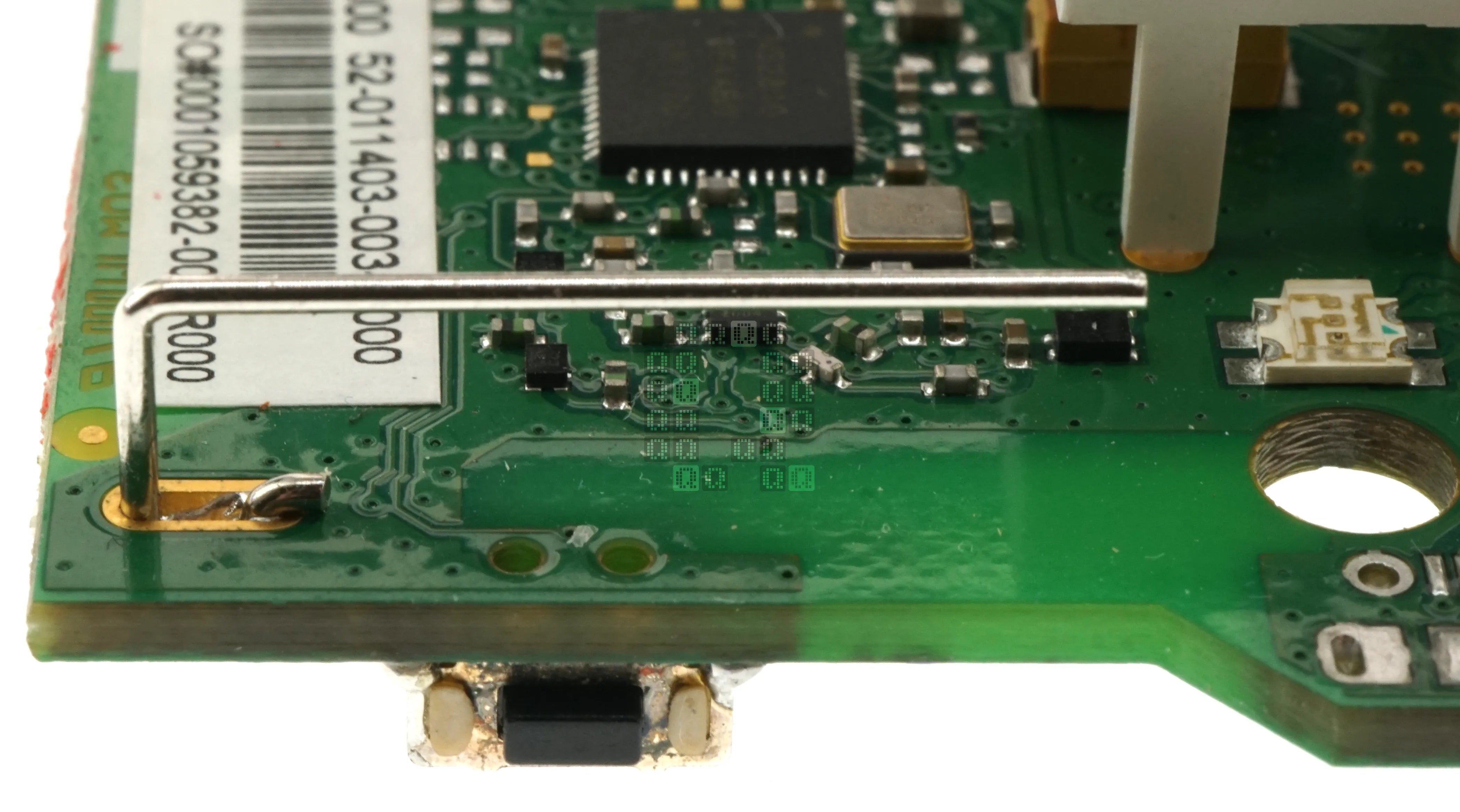
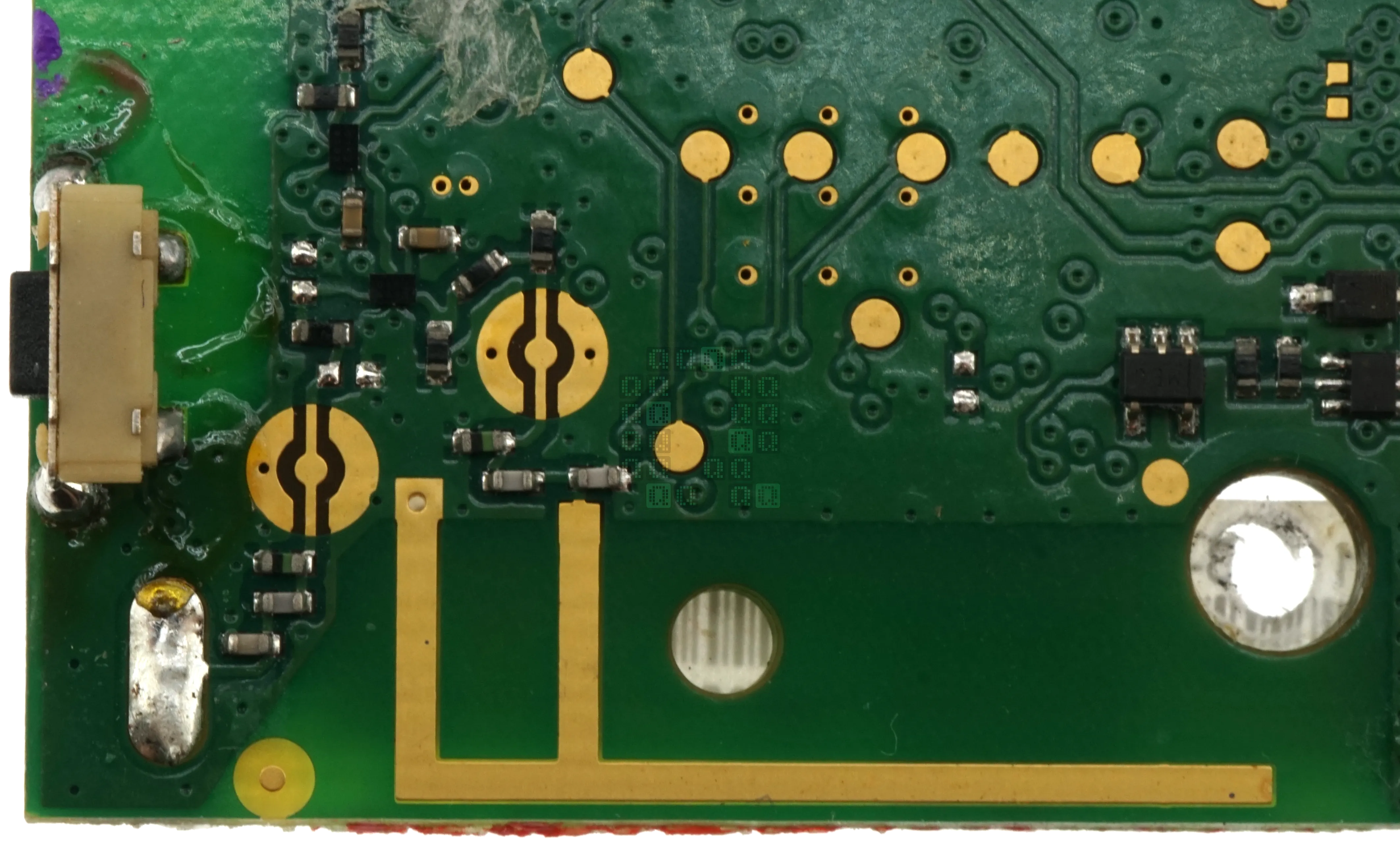
We'll finish up the circle by looking at the two antennas. I know next to nothing about the designs; there do appear to be two sets of pads for external antenna connectors. I also spy two tiny transistors that may be amplifying/splitting the signals between the antennas. Perhaps someone knowledgeable in these arts can weigh in here to explain the design?
- Other items of interest -
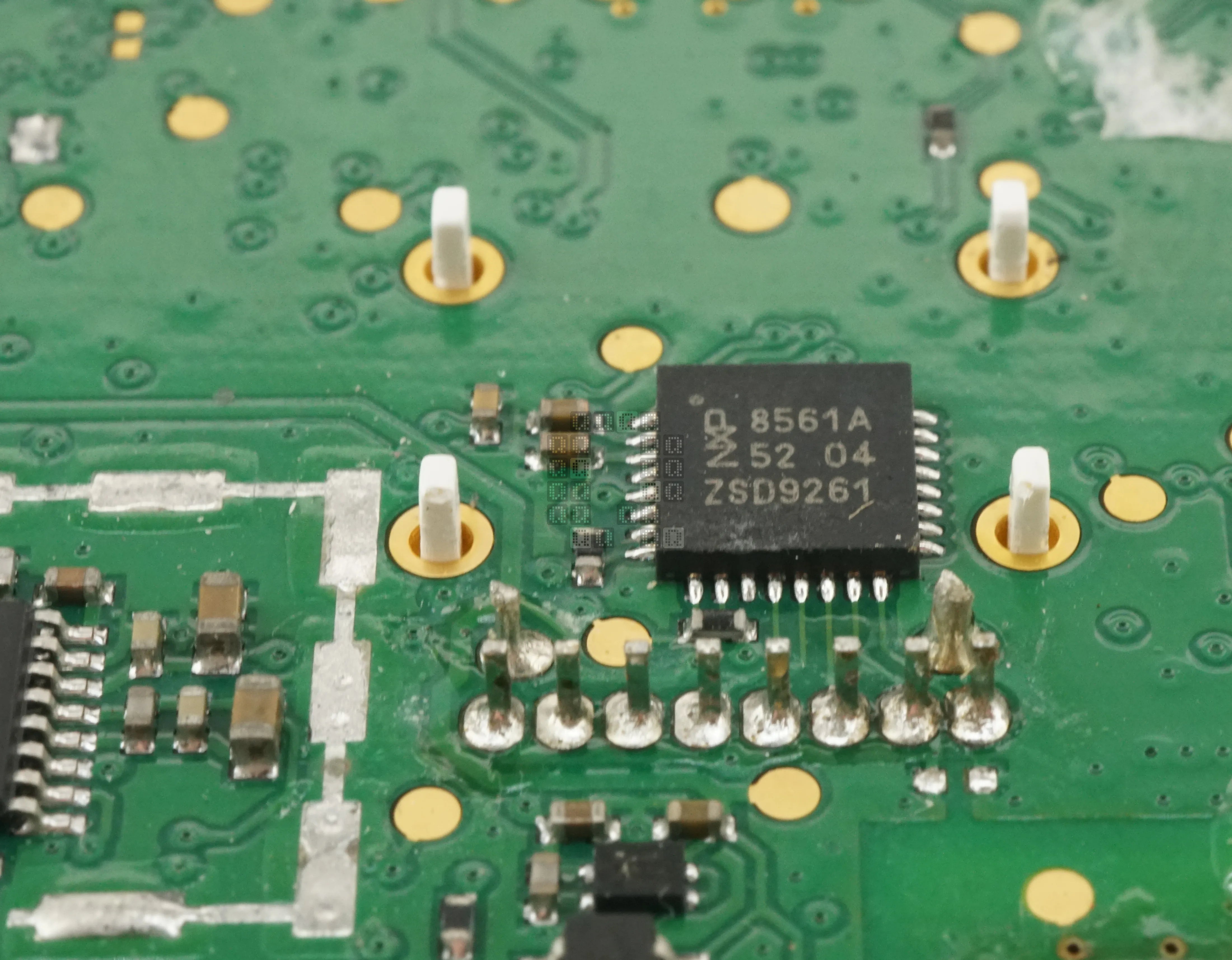
NXP 8561A 18x4 LCD Segment Driver with SPI and I2C busses. Connects to the 10 pins of the LCD Datasheet for the NXP 8561A (PDF, 688KB)
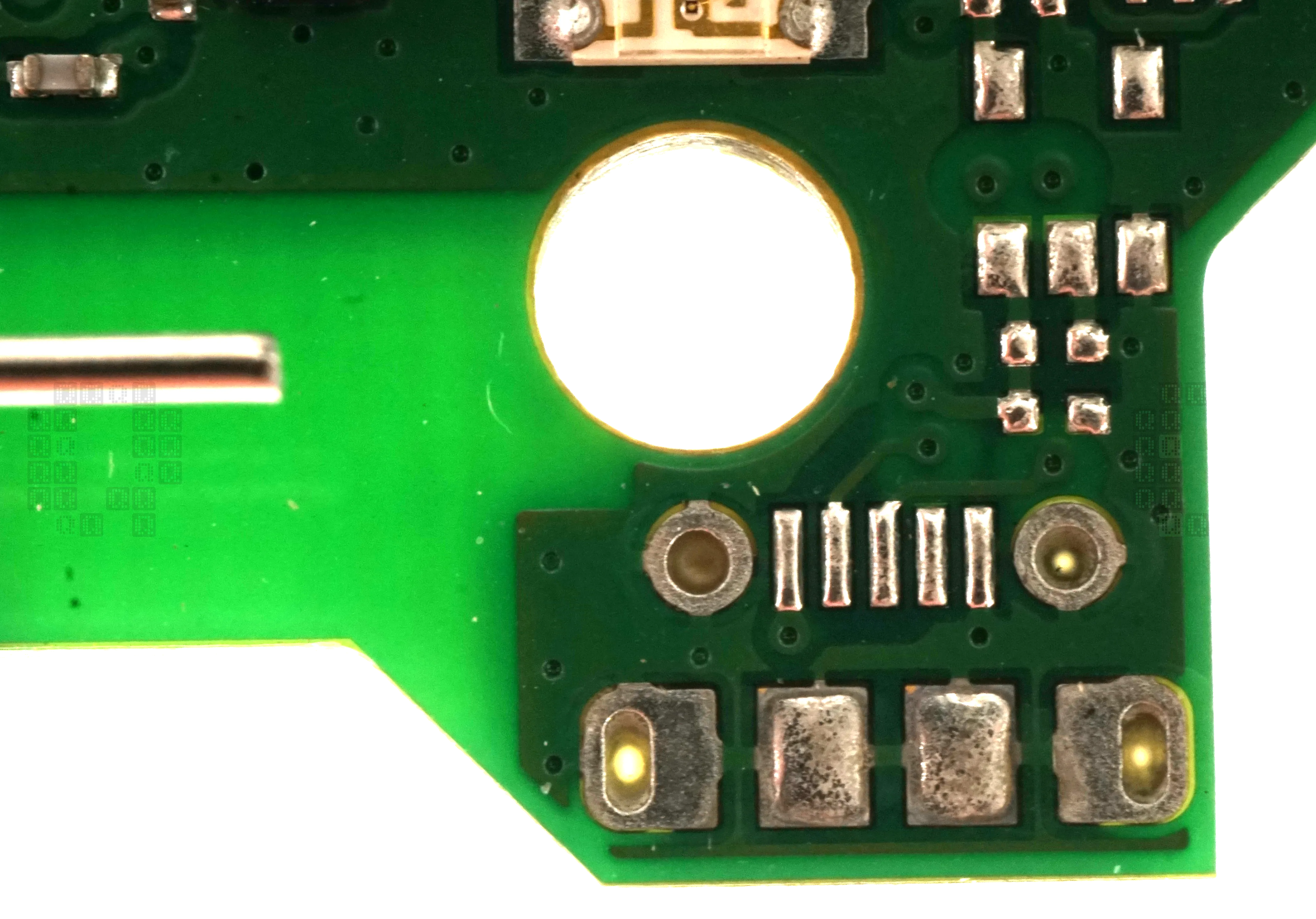
AKG appears to have laid out everything required for a USB port. Except the USB port and enabling components, of course.
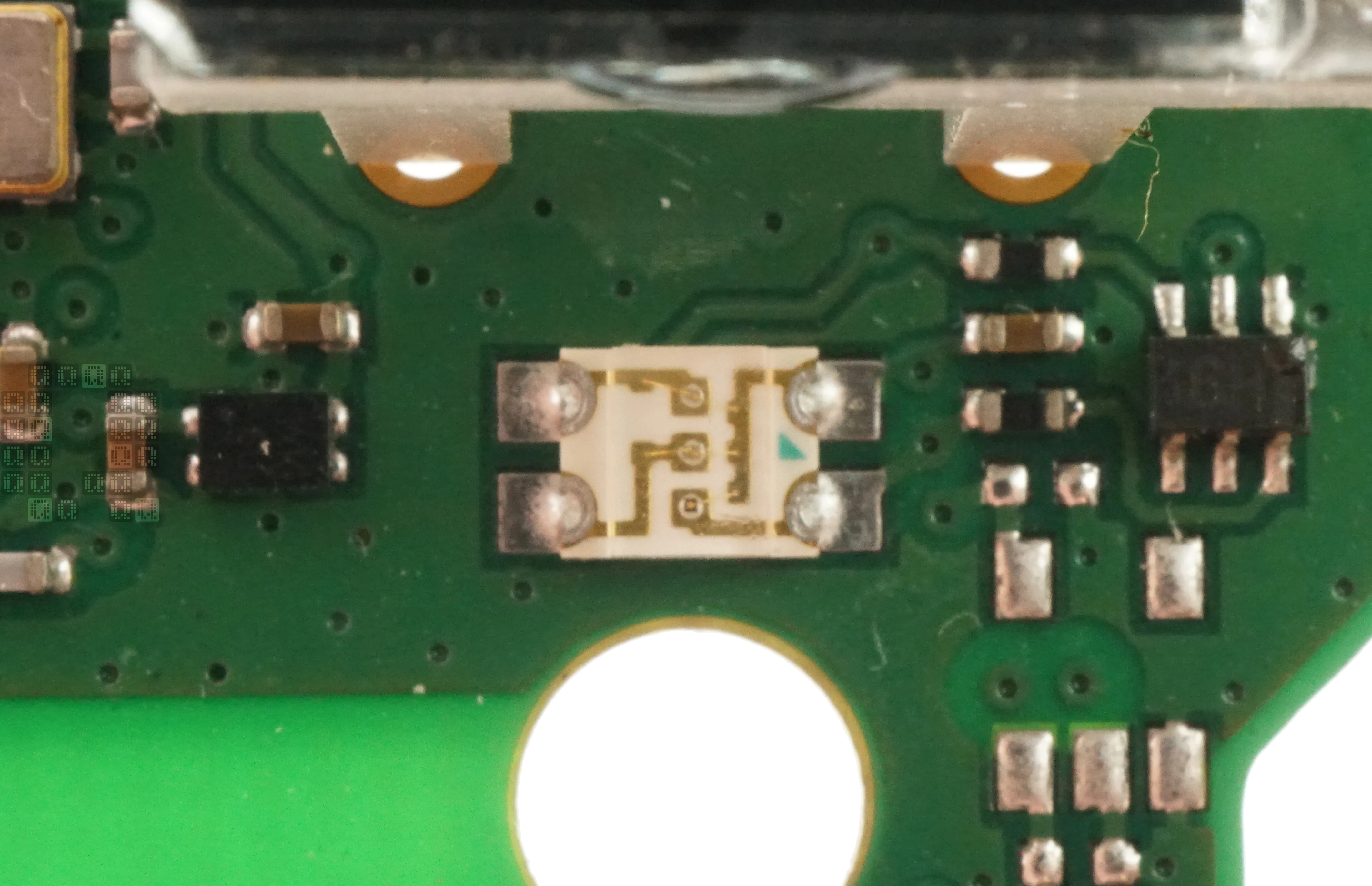
RGB LED Indicator Light - but wait - This LED only displays Red or Green when in use and there are only two resistors. Blue does not appear to be active, but that empty space for a resistor is interesting.
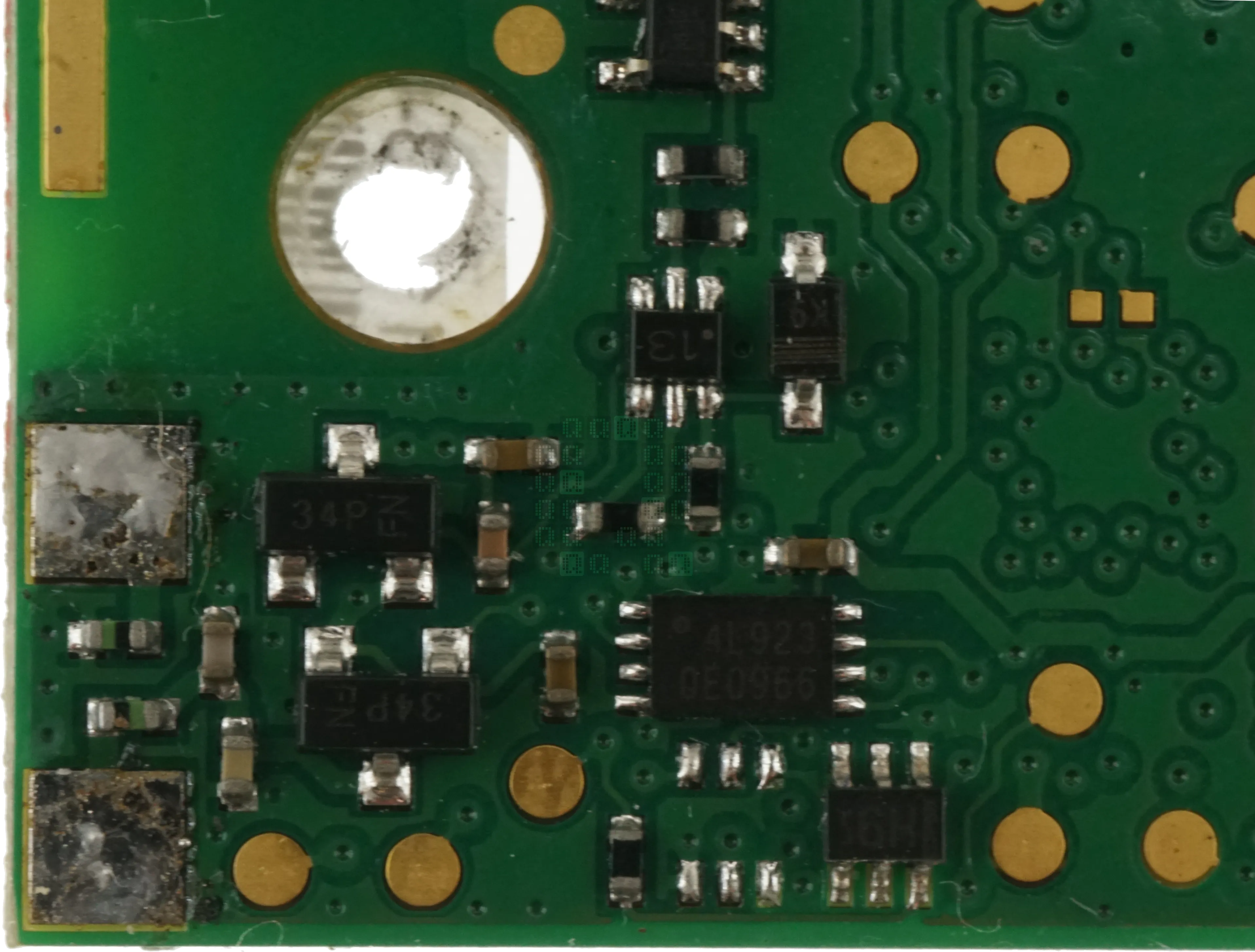
Battery/Power Regulation circuit. I thought for sure I had finally found the 8-pin EEPROM for the Renesas Dialog DA14195, but alas, it appears to be an optoisolator of some type (4L923). Unfortunately I failed to find any sort of external memory. Perhaps it is one of the 6-pin ICs or I just missed something in the datasheet?
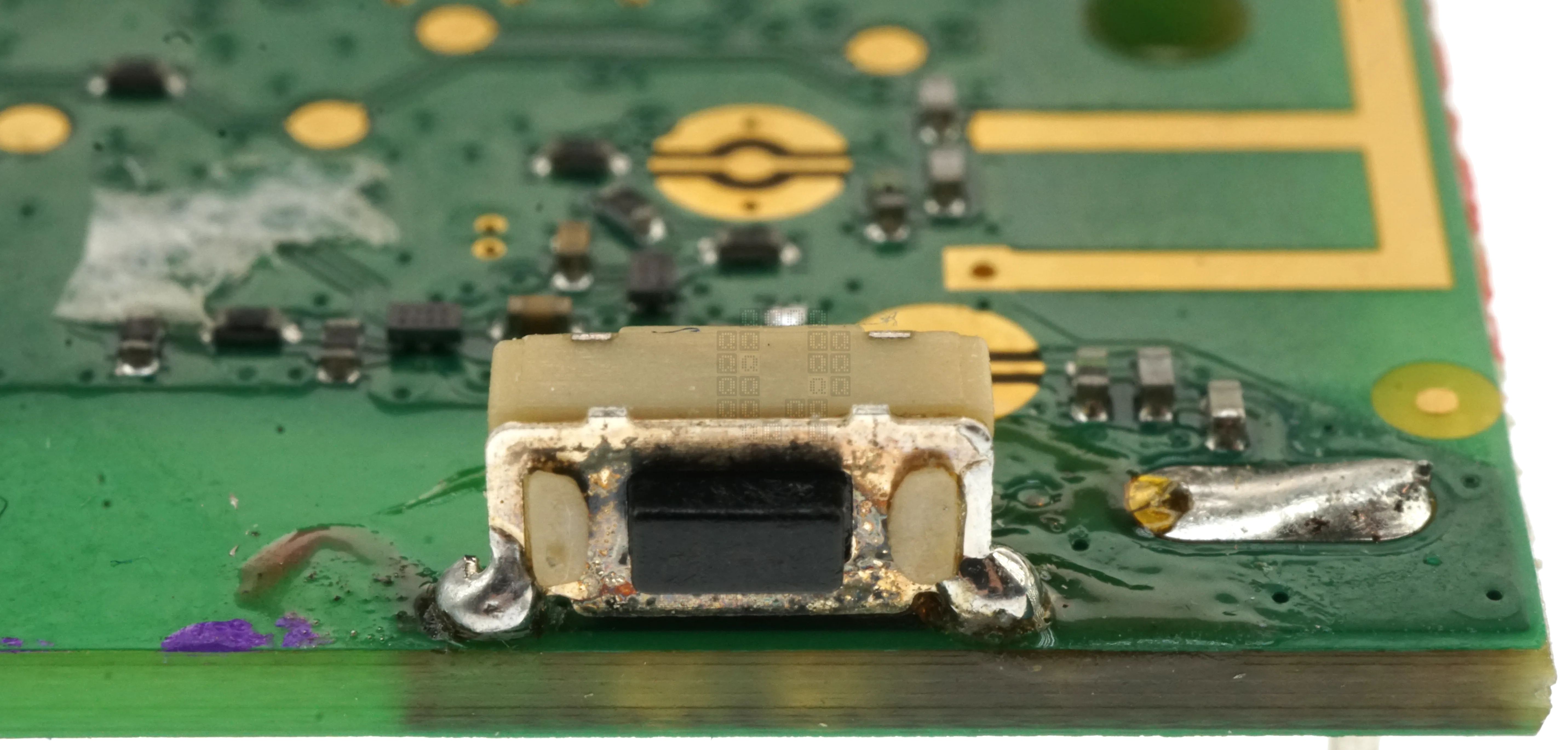
On/Off/Mute SPST Momentary Pushbutton. Looks kinda like some manual work here.
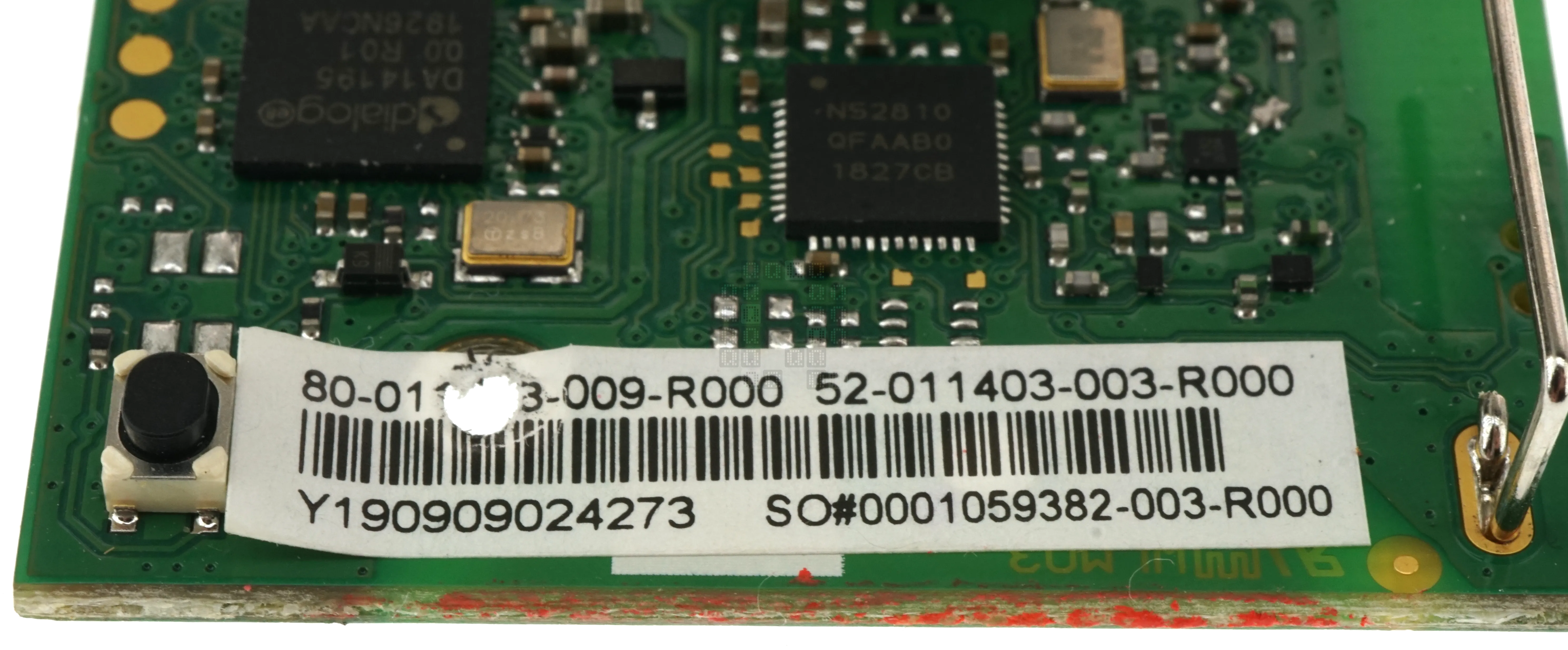
(This is the only closeup I took of the sync pushbutton) Label on the circuit board.
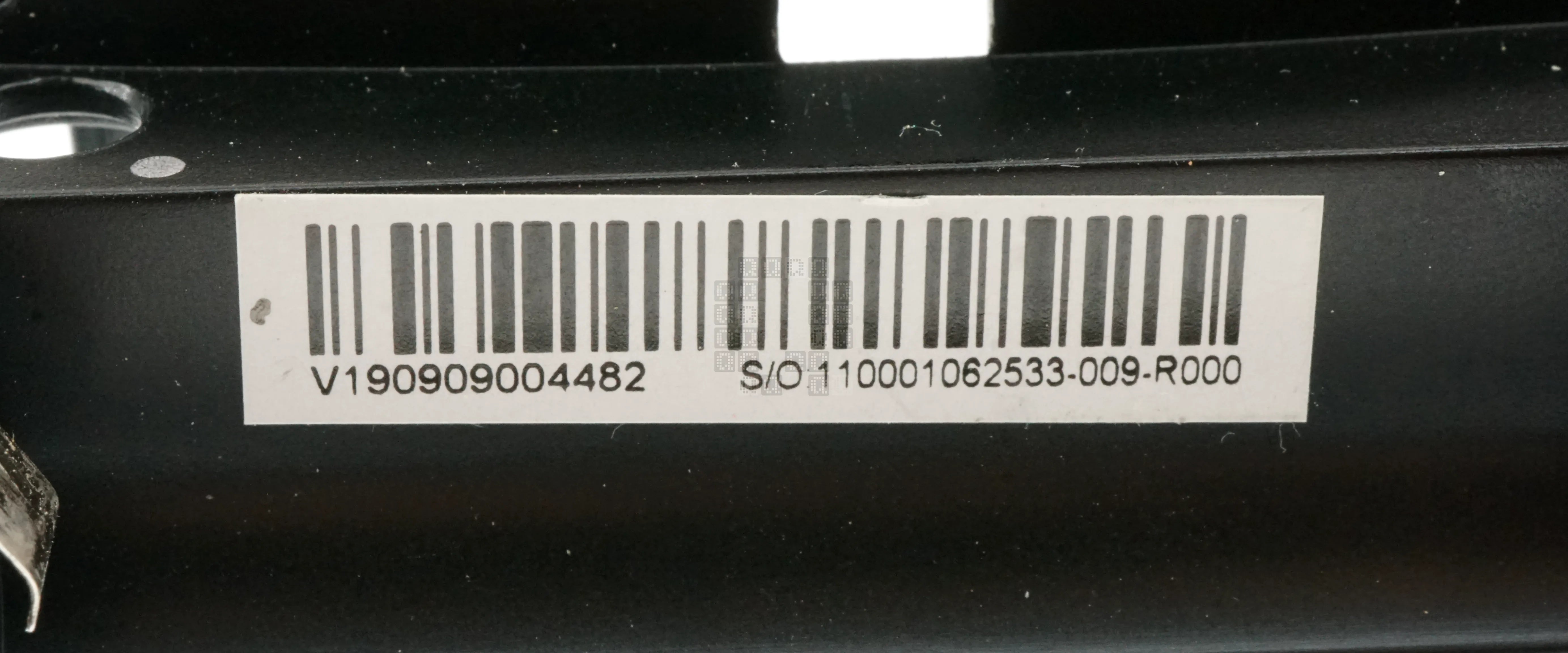
Additional labels found on this particular unit in the battery compartment.
We'll end the teardown here. As stated before, please don't buy this unit. There are issues with the jack design. And interference is a problem with this unit. 2.4GHz Wifi. Other bluetooth devices. A microwave. People in the way (this is a line-of-sight unit). In today's world there is too much that can interfere with the signal. They were having problems keeping 1 dot of signal (a dot + 3 bars is the signal strength indicator on the receiver; no dot - no signal at all.) at 60 feet with 150 people in the room. (transmitter in front on belt or in front pocket, receiver in back of the room) dot + 1 bar is all that could be achieved in optimal empty-room conditions with direct line of sight. When you needed it to 'just work', it would drop out at completely random times - once or twice in every 45 minute session - which is embarrassing to the presenter and the sound guy. There was also the weird sound tic in every recording using these units - just tiny little spikes and valleys - sorta like packet sync/connection stability problems - visible in the waveforms and occasionally noticeable in the audio playback. These units might work in specific situations, but at least make sure your entire audience has their phone on airplane mode if you use these.
As always, comments and further information are welcome!