
2022-11-10: Introducing a slight step up from the Stearns CV SINPACS. This unit is a SAMUSCO ECS224L 240V 50/60Hz 24A 60°C Electronic Centrifugal Switch. Its a step up as far as the number of parts and a couple steps down in price.
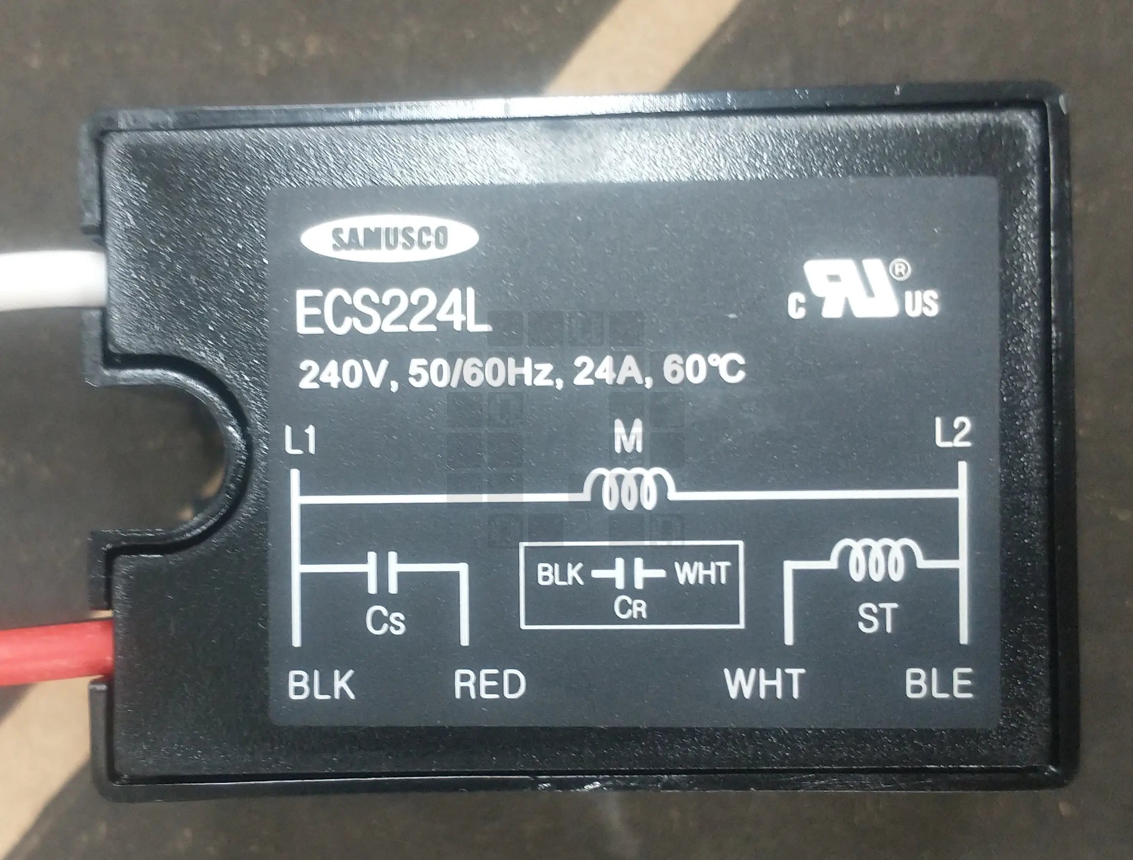
Yup. Looks exactly like the product pictures. DATASHEET HERE (PDF, 1 Page, 174kb)
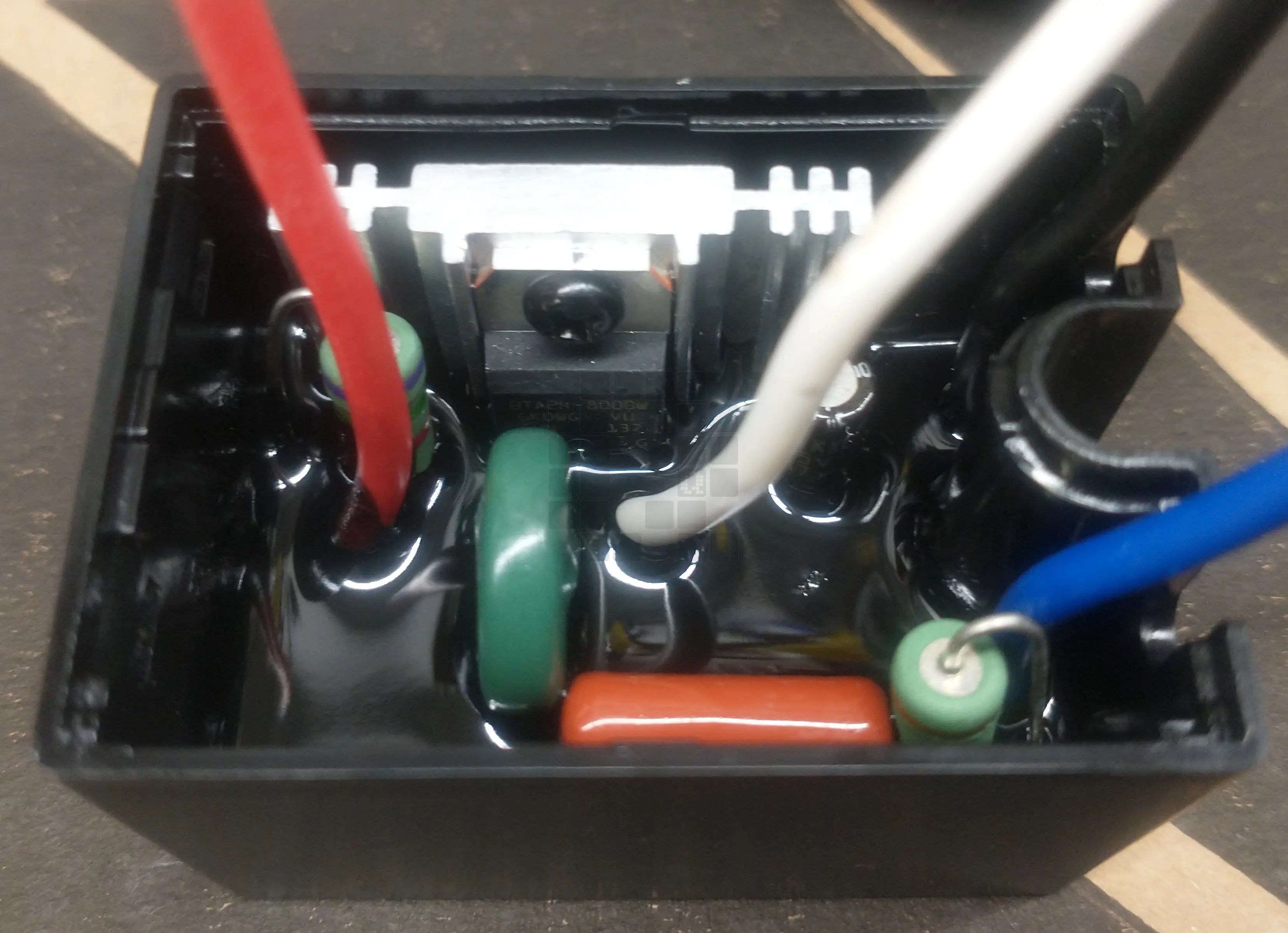
Top Cover Removed. Nicely potted and a nice aluminum heatsink on the TRIAC.

It wasn't too hard to reach the bottom of the board. A 6 pin test connection strip?
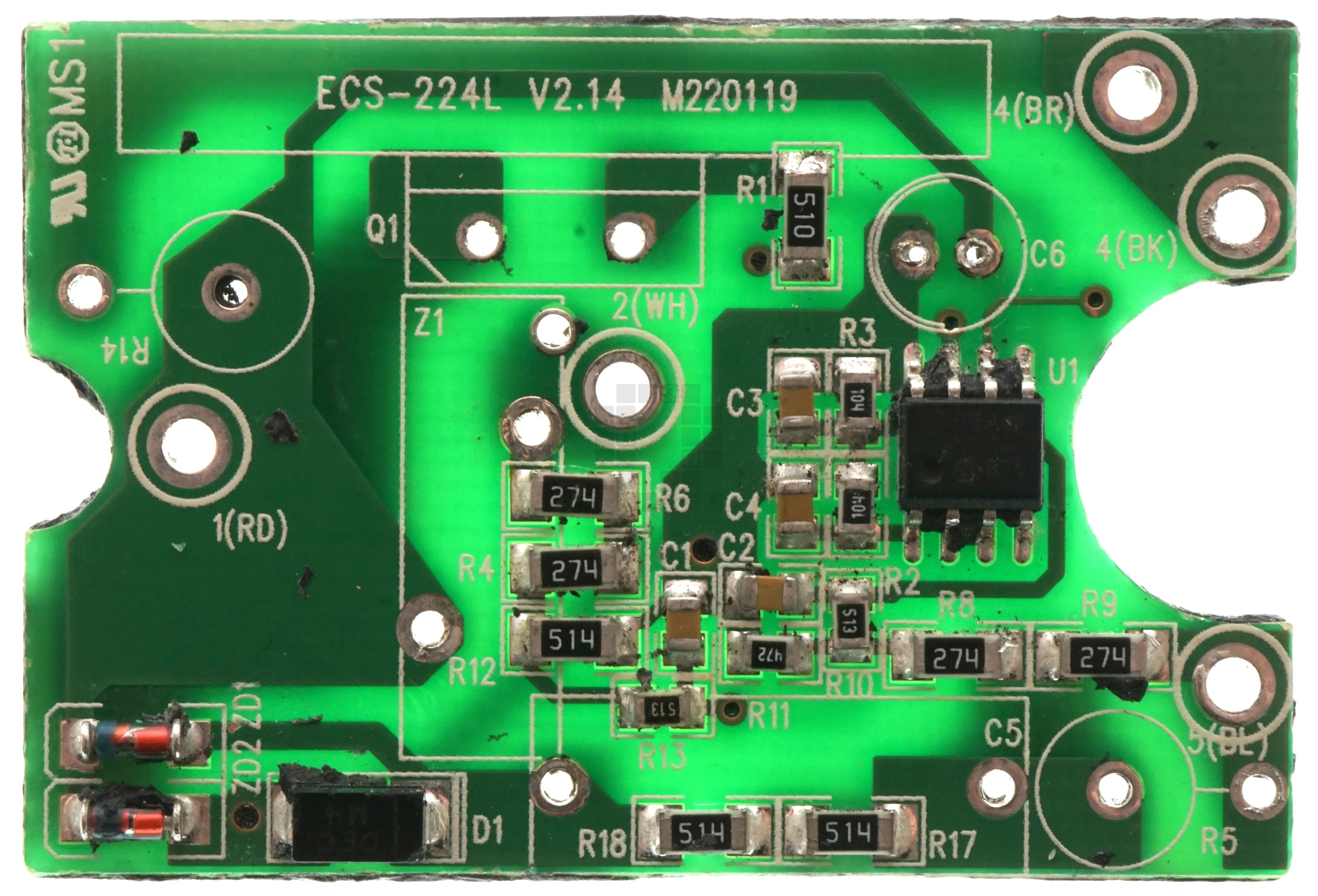
Pretty Picture of the top of the circuit board with the through hole components removed.
Board is labeled ECS-224L V2.14 M220119

U1: MCV08A I/SN - I think this may explain the MCU noted in the description. hmm... a copy of the code might be helpful at some point...That and a datasheet in english.
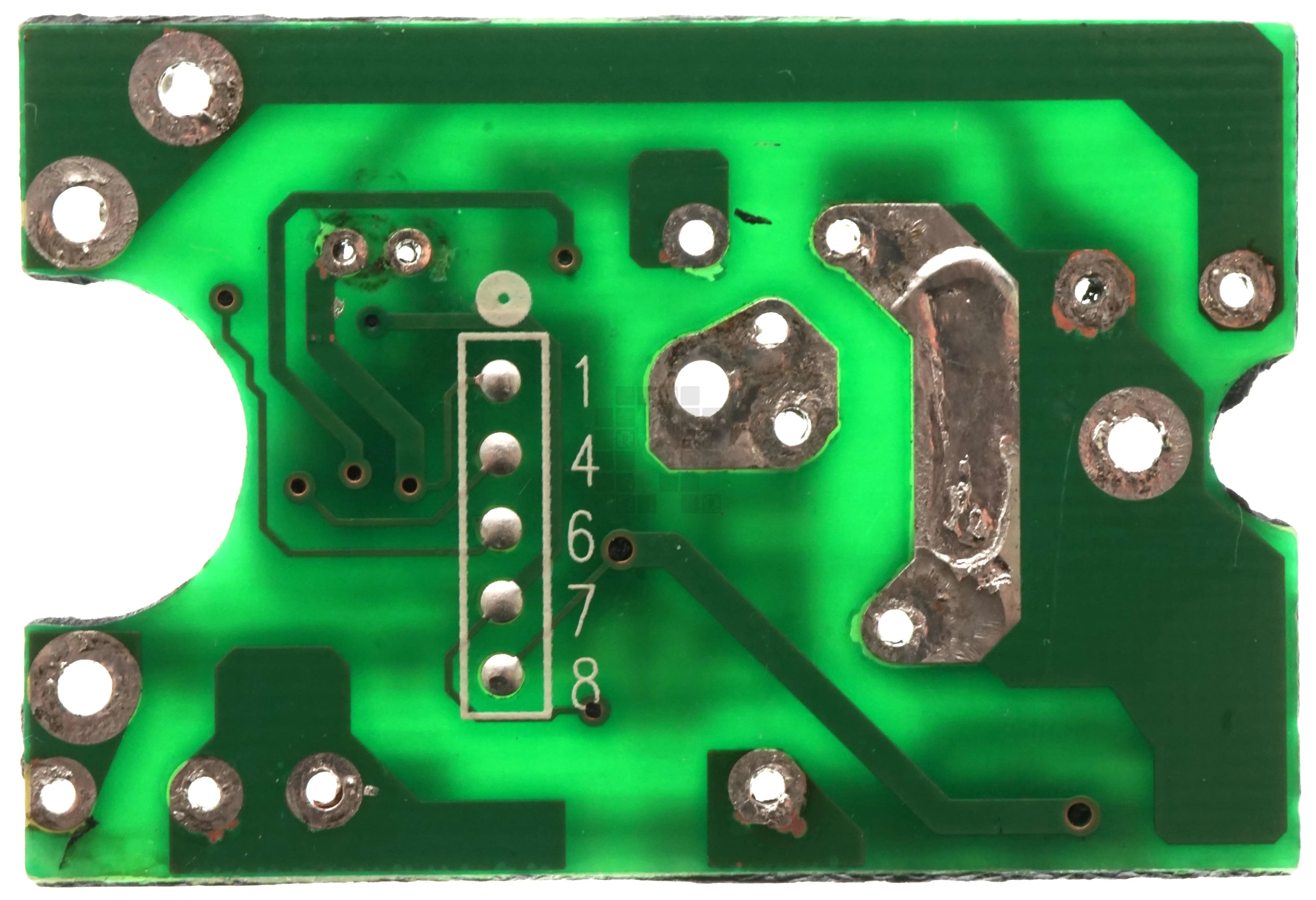
Pretty picture of the bottom of the circuit board.

Huh... This is a 220/240VAC unit... Any chance they put a zero ohm resistor in place of one of each resistor combo (R4/R6, R8/R9 and R17/R18) to make it a 110/120VAC version?
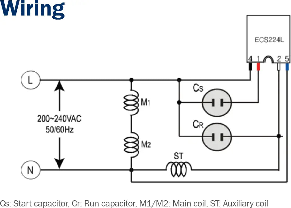
This is the wiring diagram from the datasheet above for a little context on how this unit is used. One notable difference between this and the Stearns CV series is that this unit allows the use of a Run capacitor. (this unit would be equivalent to their CVR series)
If you or someone you know finds this info useful and decides to start building something similar, please let us know. We'd like a royalty check and the option to buy some of your devices. ;)
Note: All electrical diagrams are believed to be correct as far as we're aware; however, there may be mistakes and omissions. You assume any and all risks by using these diagrams for anything other than a pretty picture to look at.
Part 1 of the un-obtainium saga: the CV40-165