
Please Note: Clicking on an image will take you to a higher resolution version of the image you clicked on.
2026-07-25: It started with a power outage and downed trees. Which then resulted in me realizing every last one of my 9.0/12Ah M18 batteries were out of balance and were incapable of running my chainsaw for more than 15 minutes. This resulted in me logically buying a brand new battery. (and rebalancing the packs when I got power again.) And since its mine, I can do anything I like with it... Including opening it and exploring the insides. Enjoy!
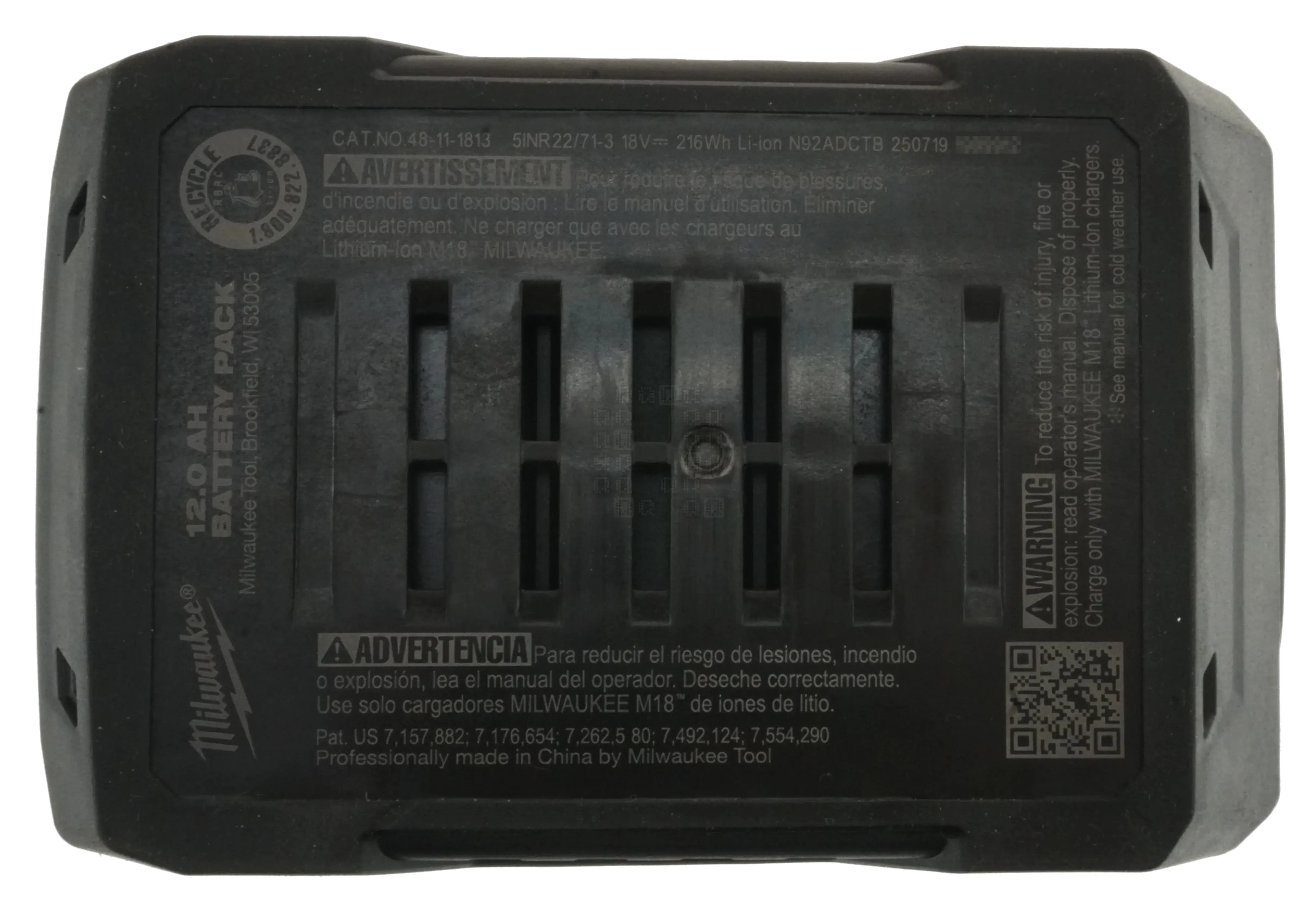
This battery pack is the Milwaukee 48-11-1813 also known around the world as the 5INR22/71-3. Milwaukee rates it for 18VDC and 216 Watt-hours. My battery was made on 2025-07-19, so it is about a year old already. One new thing to notice on the bottom is the 'Cool-Cycle' vents.
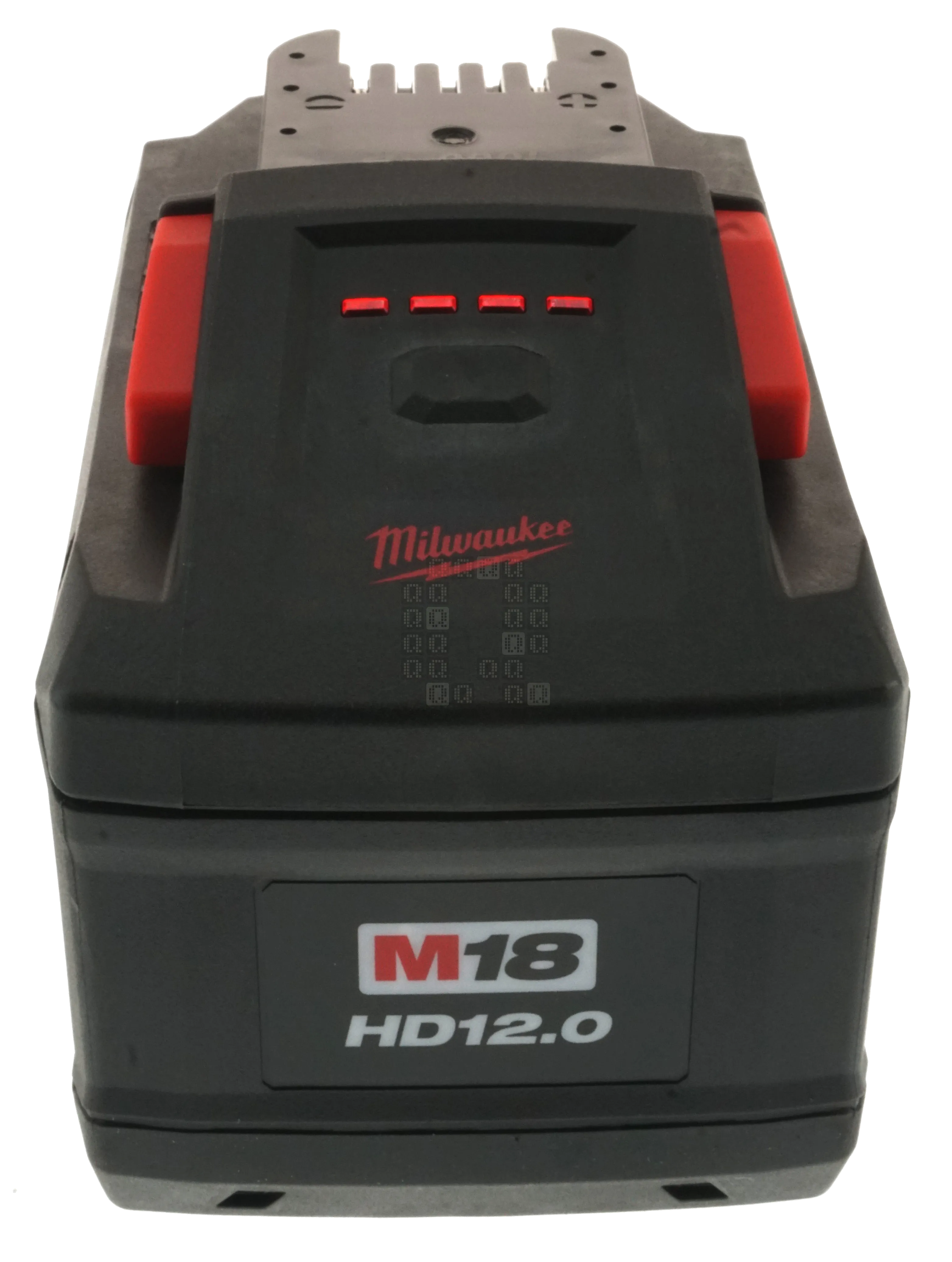
On the front, we're greeted with the normal test button and 4 red Status LEDs. Press and hold the button for 5-10 seconds and you are greeted with diagnostic blink codes. (I do not have a nice concise written explanation for them).
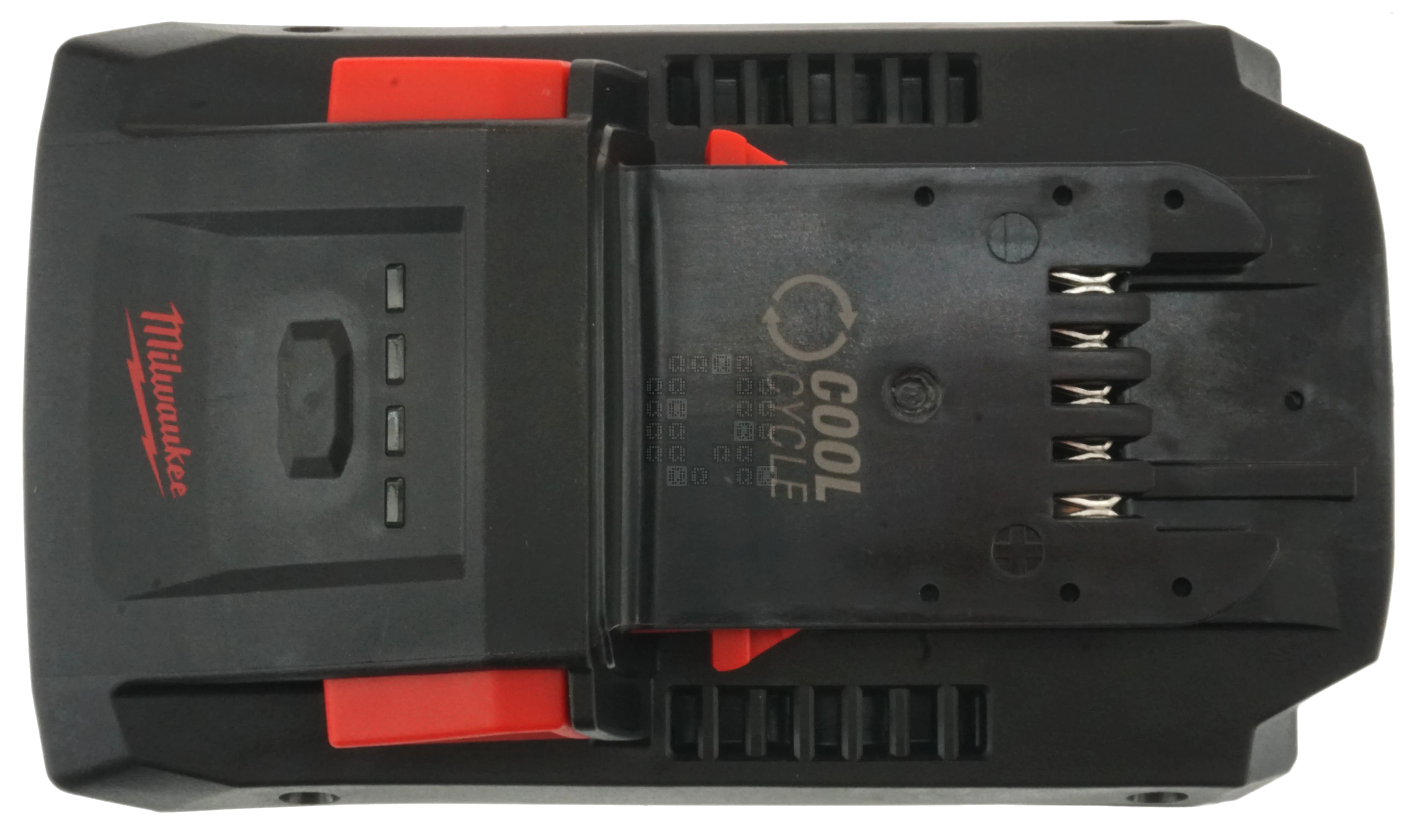
Looking at the top shows the standard 5 Pins - they've included a handy positive (+, bottom-most pin) and negative (-, topmost pin) label embedded in the plastic to tell you what the two outside pins are. Center pin is the charging input power and the other two pins are for communication. You can also see the Cool Cycle vents on the sides of the battery.
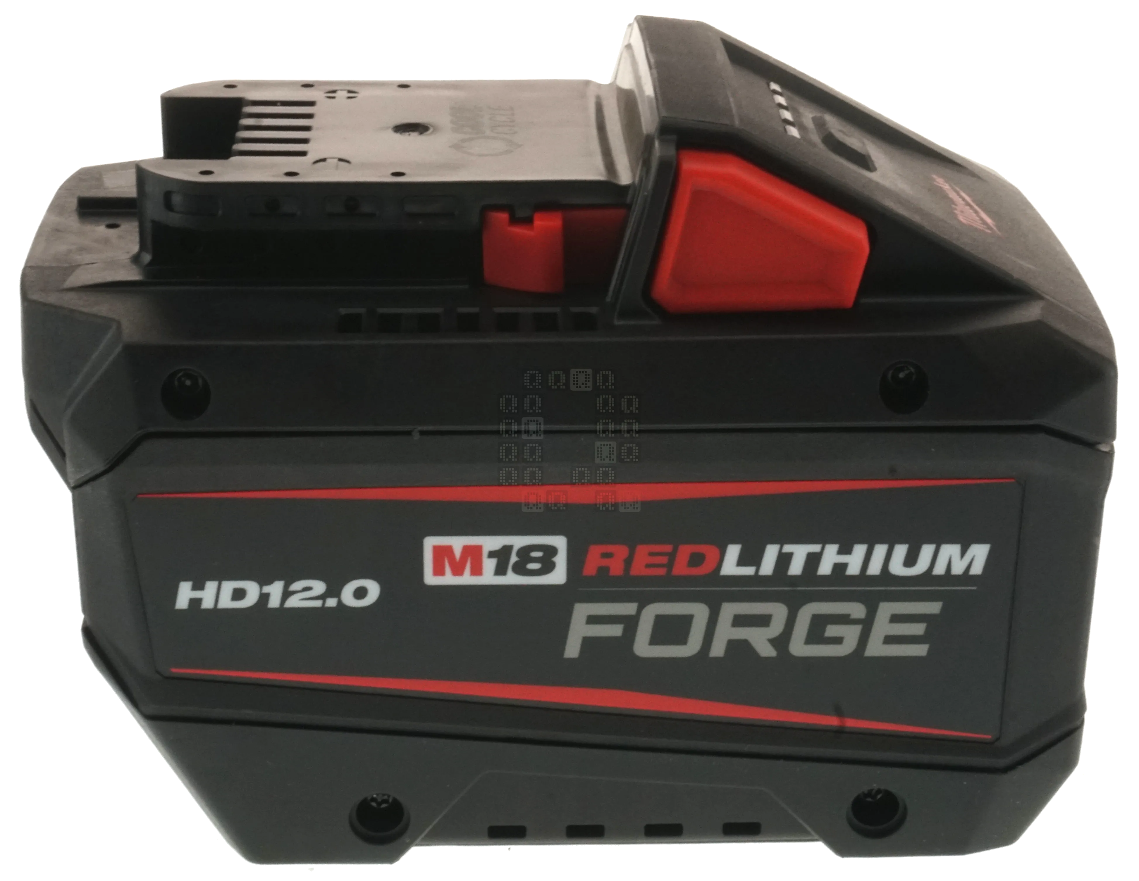
And here is a side view of the battery too, just in case. (Ok, I'm just stalling at this point. I know you want to see what is inside...)
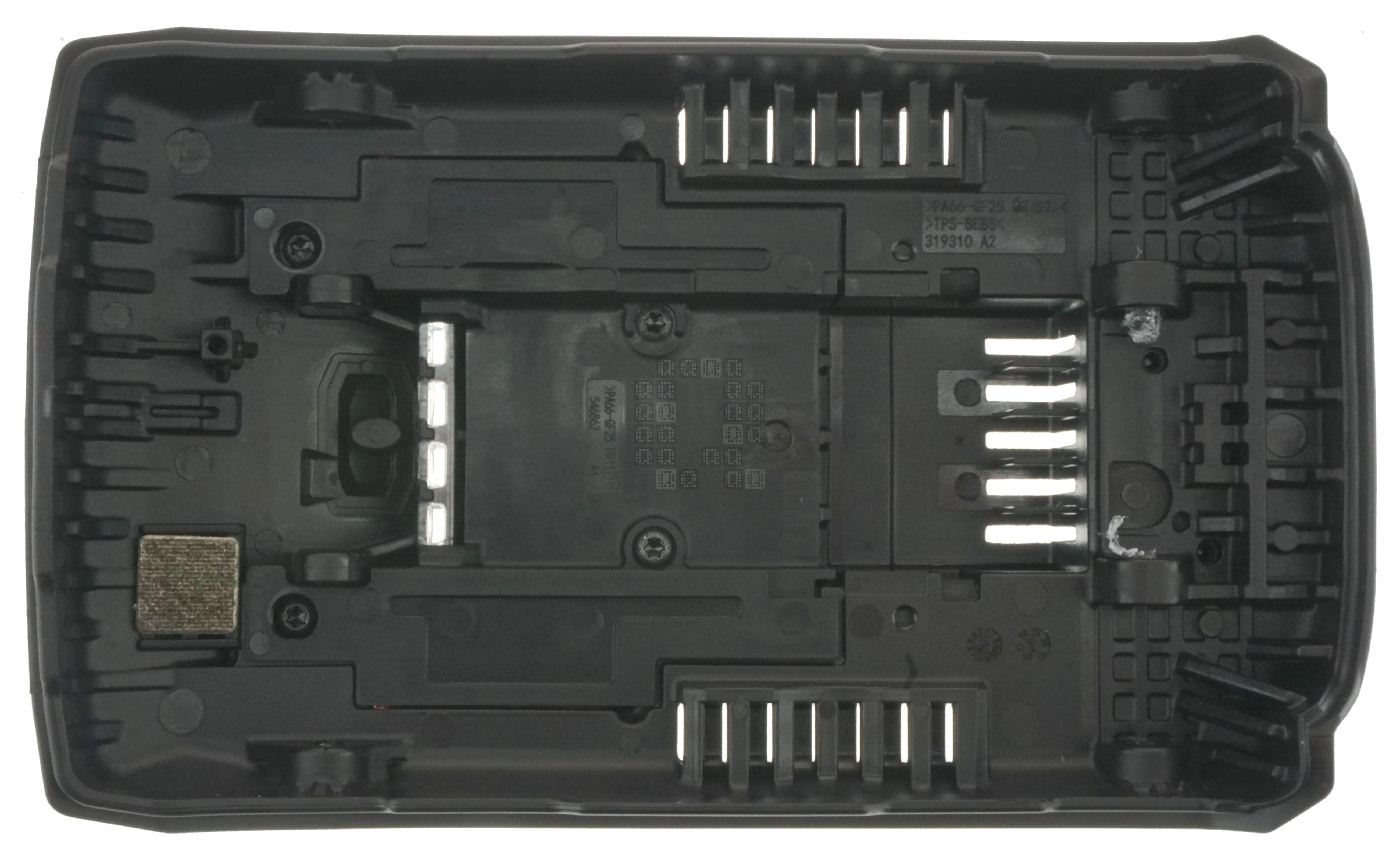
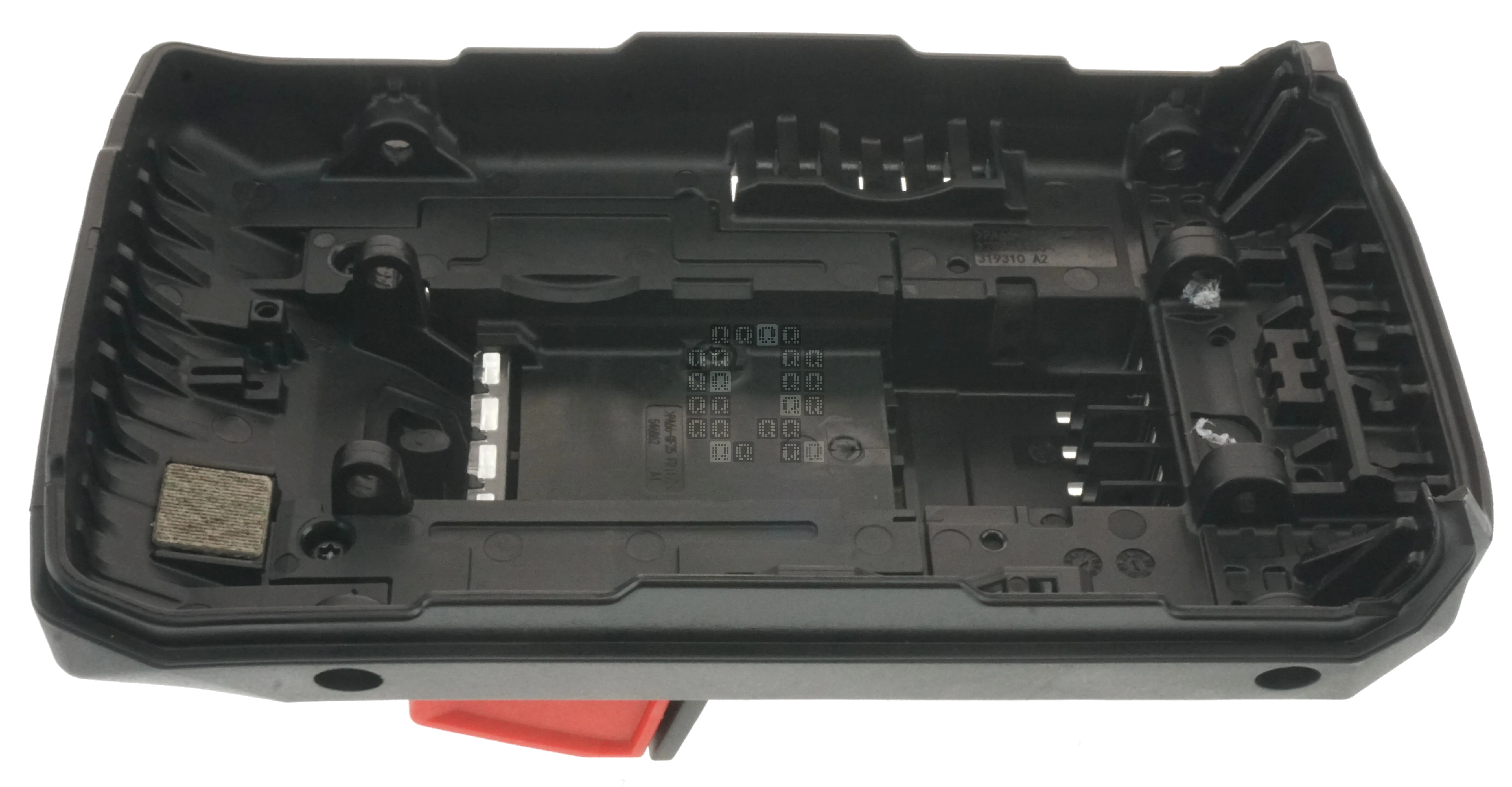
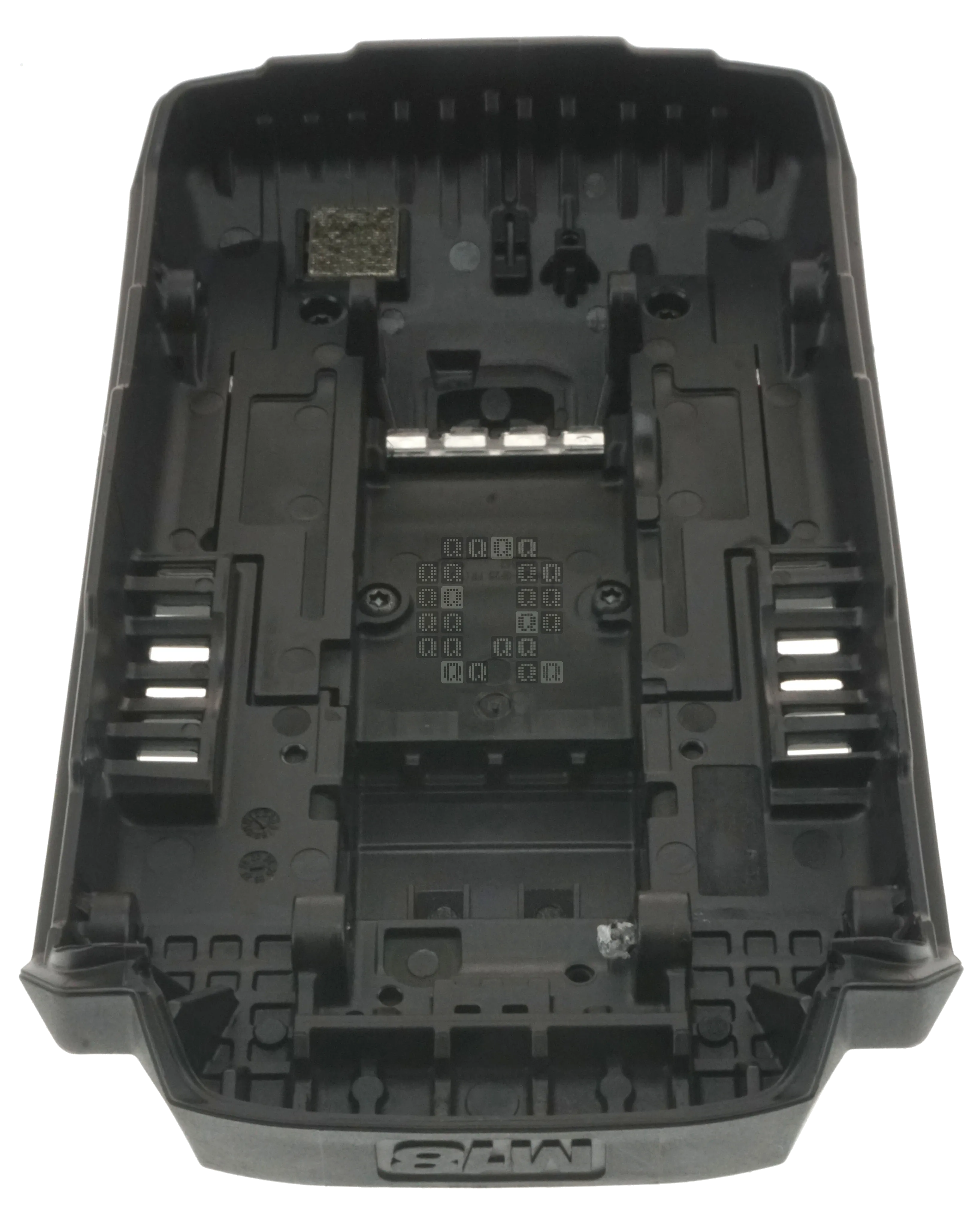
You knew this was coming, right? Inside the top cover is fairly un-exciting. The yellow square is a piece of some sort of high temp material - it presses down against the battery negative terminal 'fuse'. There are 4 screws which hold a cover that contains the latch and springs - I did not remove it or explore underneath. Case material is marked as PA66-GF25. The Cool Cycle vents are interesting from the inside - wavy - I wonder how that helps the airflow?
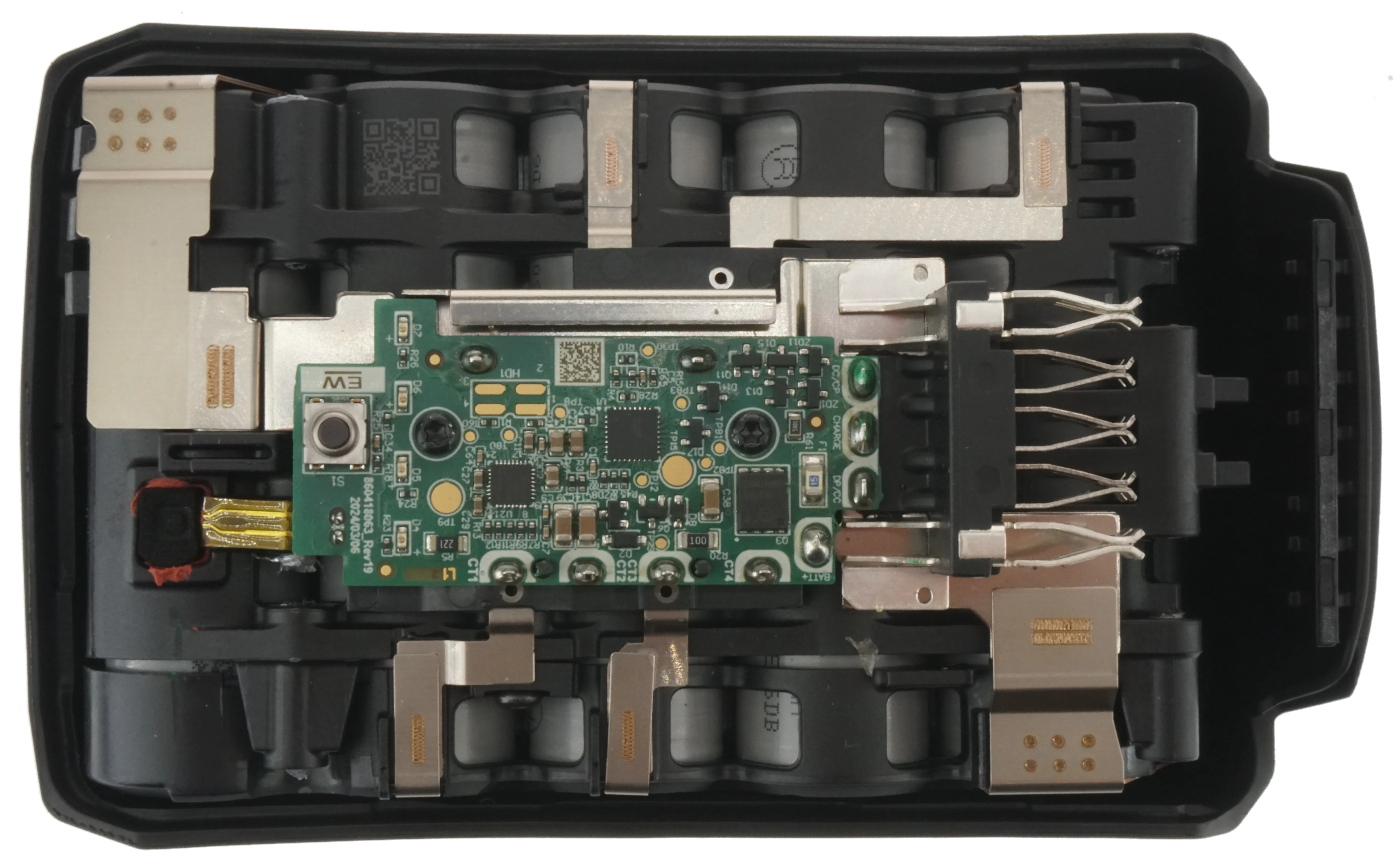
Here it is - the first peek inside. I'll zoom in on the circuit board shortly. Yellow square is the 'fuse'. Red square is the thermister. Positive battery terminal connects directly to the positive output terminal, while negative goes through the fuse and an amperage sensing section under the circuit board.
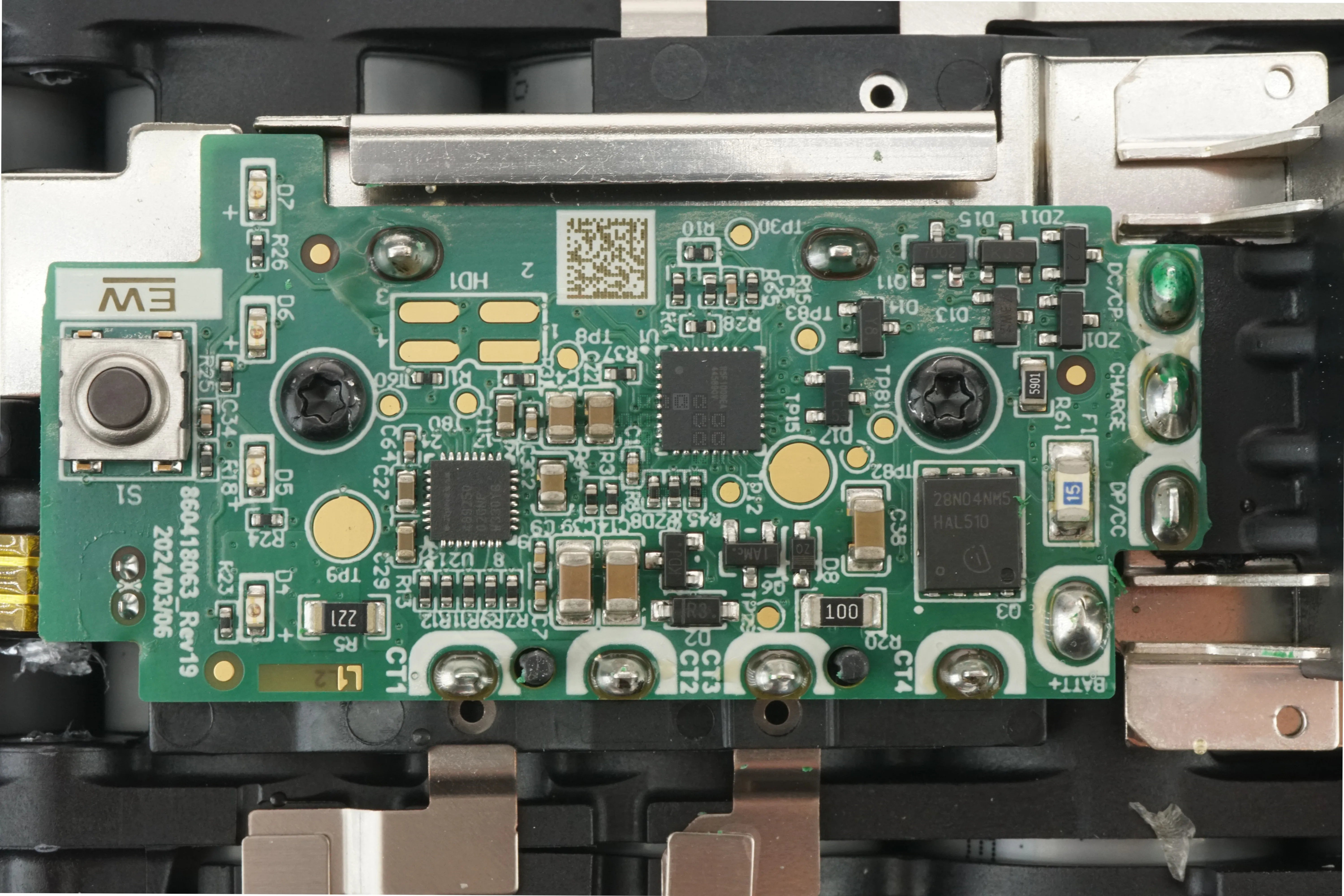
And here are the brains of the battery. Circuit board is marked '860418063_Rev19 2024/03/06'. It is a 4-layer board and components are on both sides. This is not a destructive teardown - only an exploration. All external pins are labeled quite nicely. Now for the major interesting parts:
- Magenta: These are the indicator LEDS. To the left of that is the single button. (I'm wondering about the underlined 'EW' right above the pushbutton...?)
- Green: This is the programing pins with the same arrangement as other batteries.
- Cyan: This is the charge fuse - 15 Amps.
- Red: This is an Infineon OptiMOS 5 Power-MOSFET Transistor. (Datasheet Here) This transistor controls the charging of the battery.
- Blue: Renesas R5F100BF CPU (Datasheet Here) This CPU has 96KB of Flash ROM, 8KB of Data Flash & 8KB of RAM. It has 32 pins. (I don't see a crystal on this side of the board)
- Yellow: I believe this is a Renesas RAA489250B 5-Cell Li-Ion Battery Front End. (Datasheet Here)
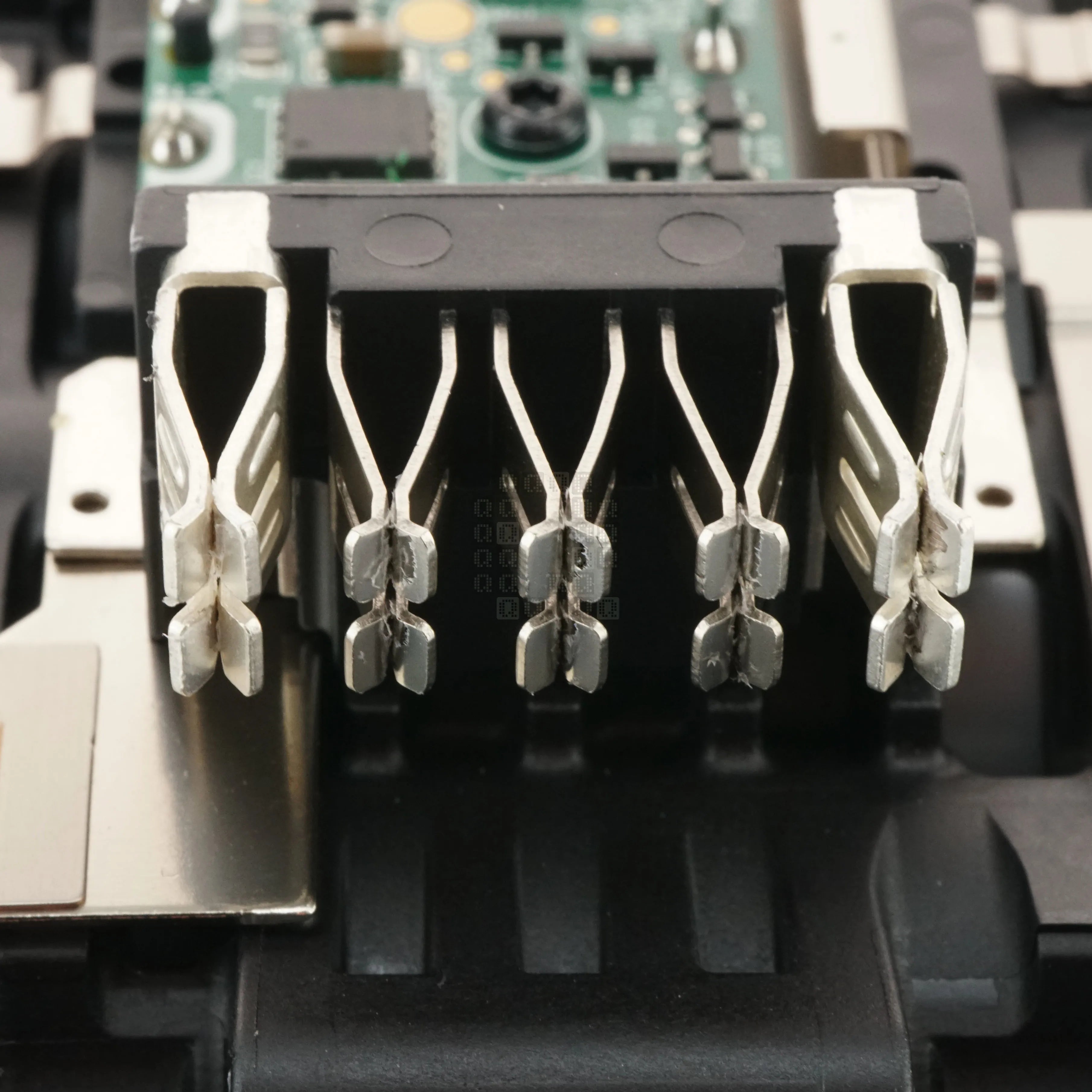
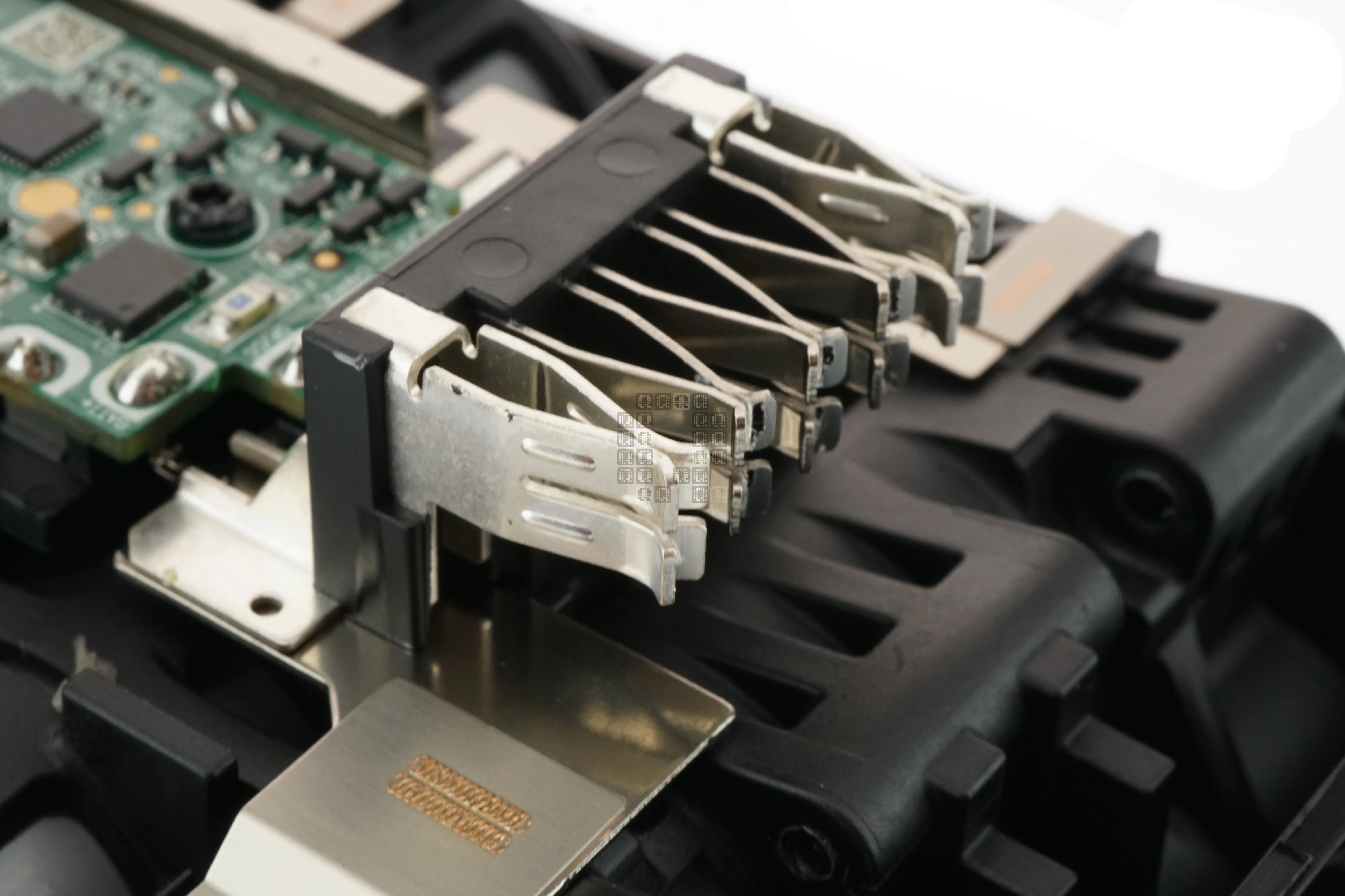
Here are two images of the terminal block. No grease on these terminals. If you notice, the two outside terminals are beefier than the other three.
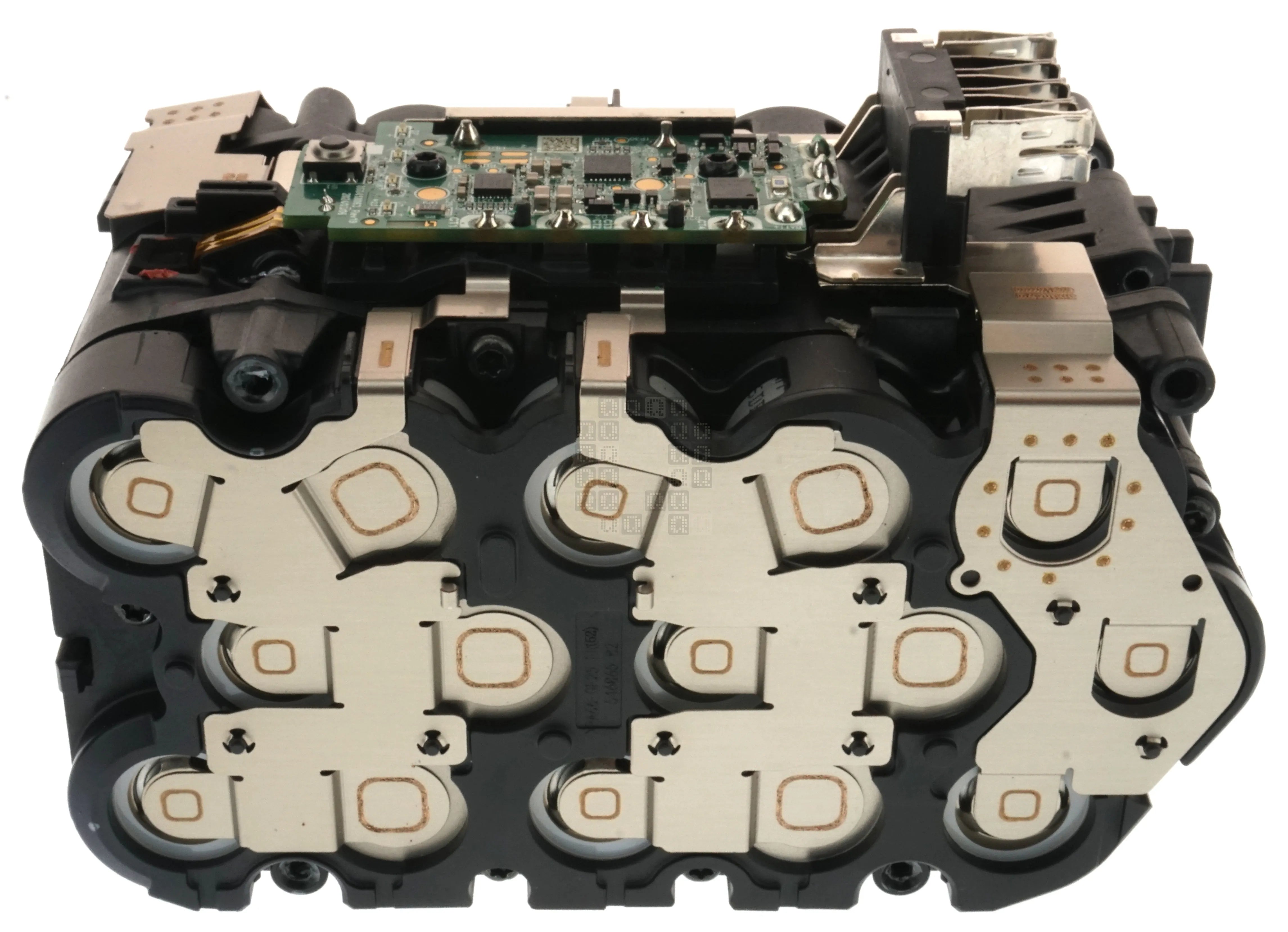
Here is the battery with the bottom cover removed. I think the laser welds are kinda neat... So I had to do some closeups:
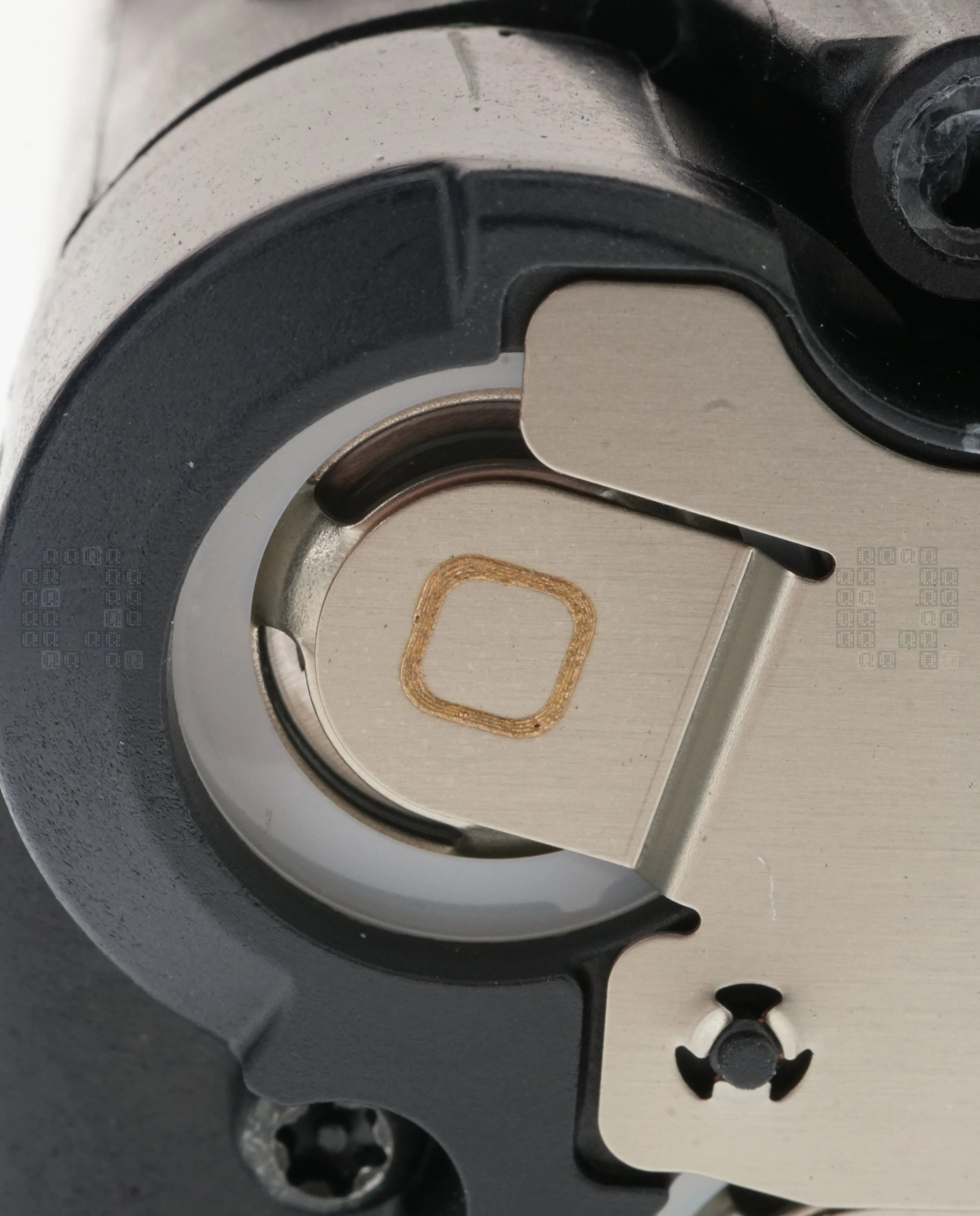
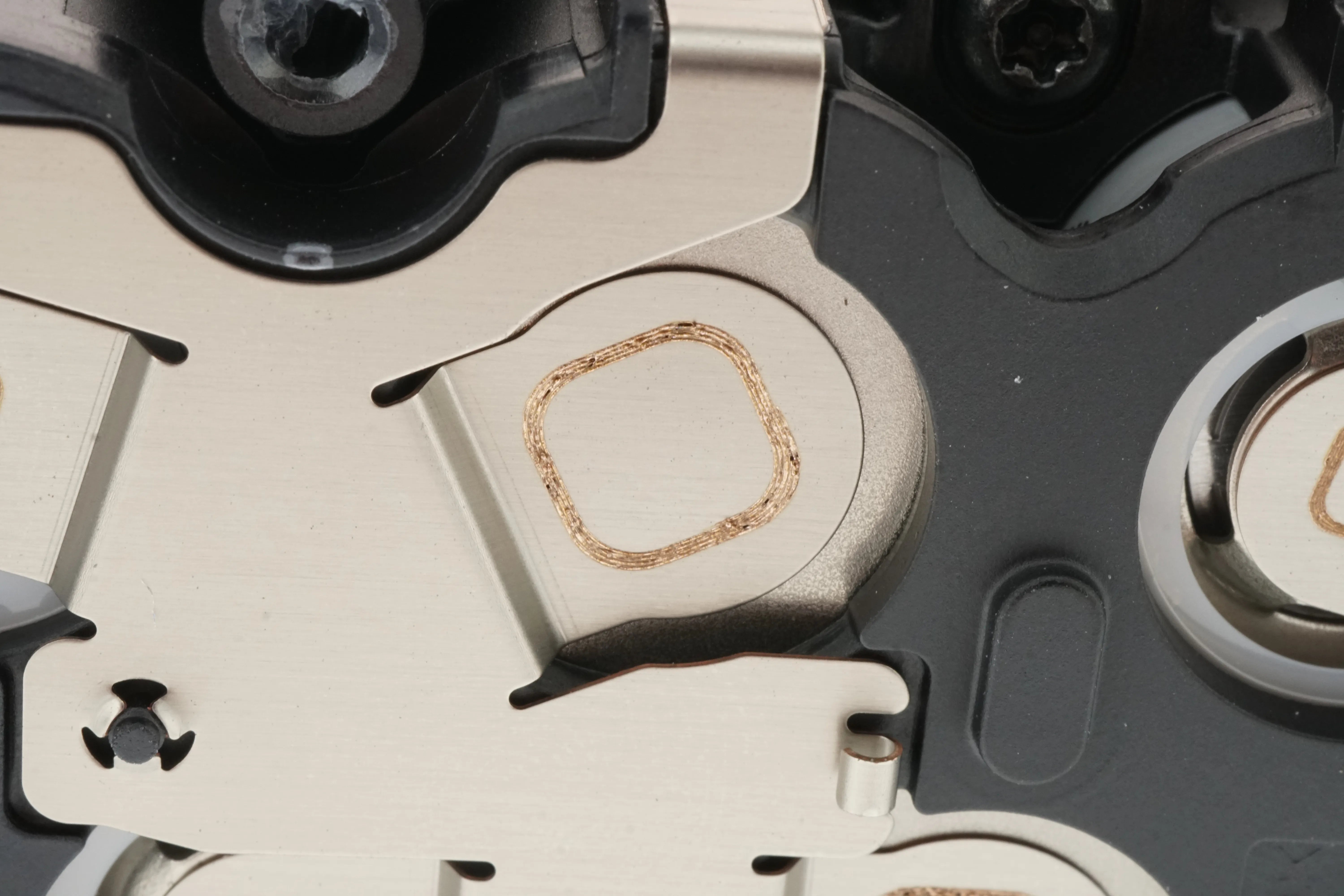
The welds are kinda pretty and delicate looking; but I'd bet they are way stronger than spot welds - I'd love to see how this is done. You'd have to clamp it somehow with enough line of sight to weld, but I see absolutely no clamping marks. If there is any sort of gap, laser welding would not work properly. There's quite a lot of engineering staring at me here!
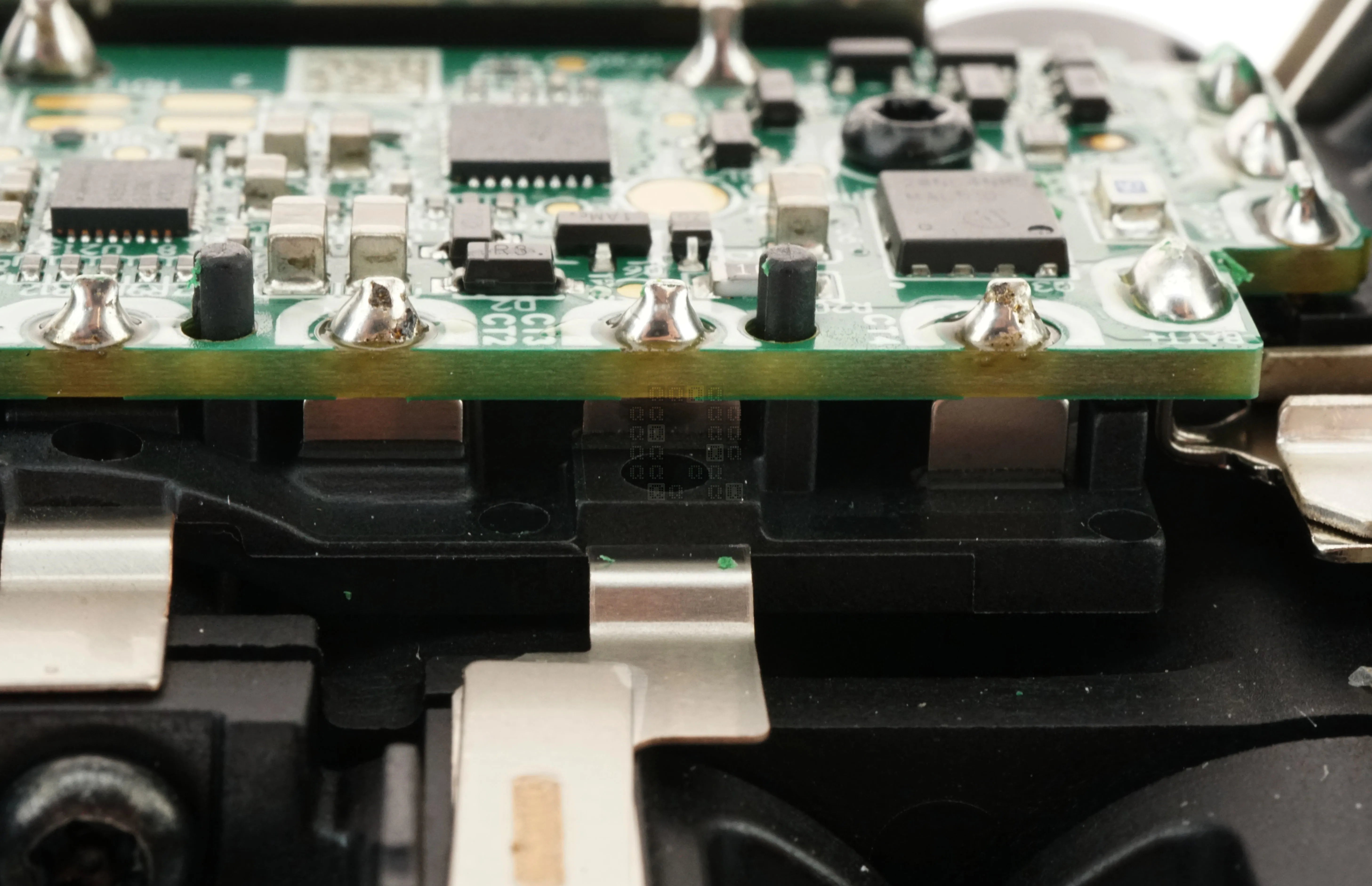
I'm going to throw this one in here too, even if its out of place: These are the battery pack connections to the circuit board.
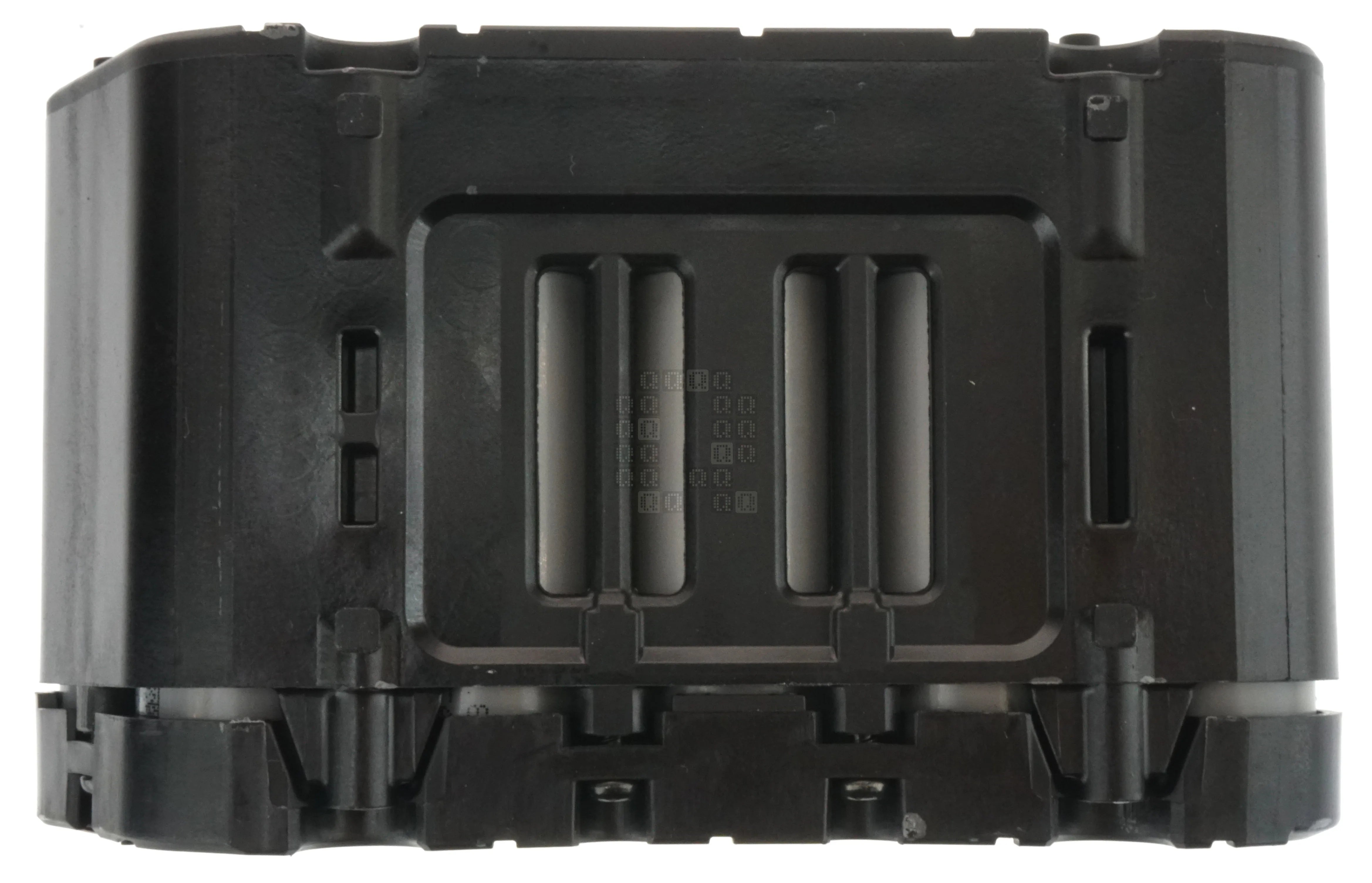
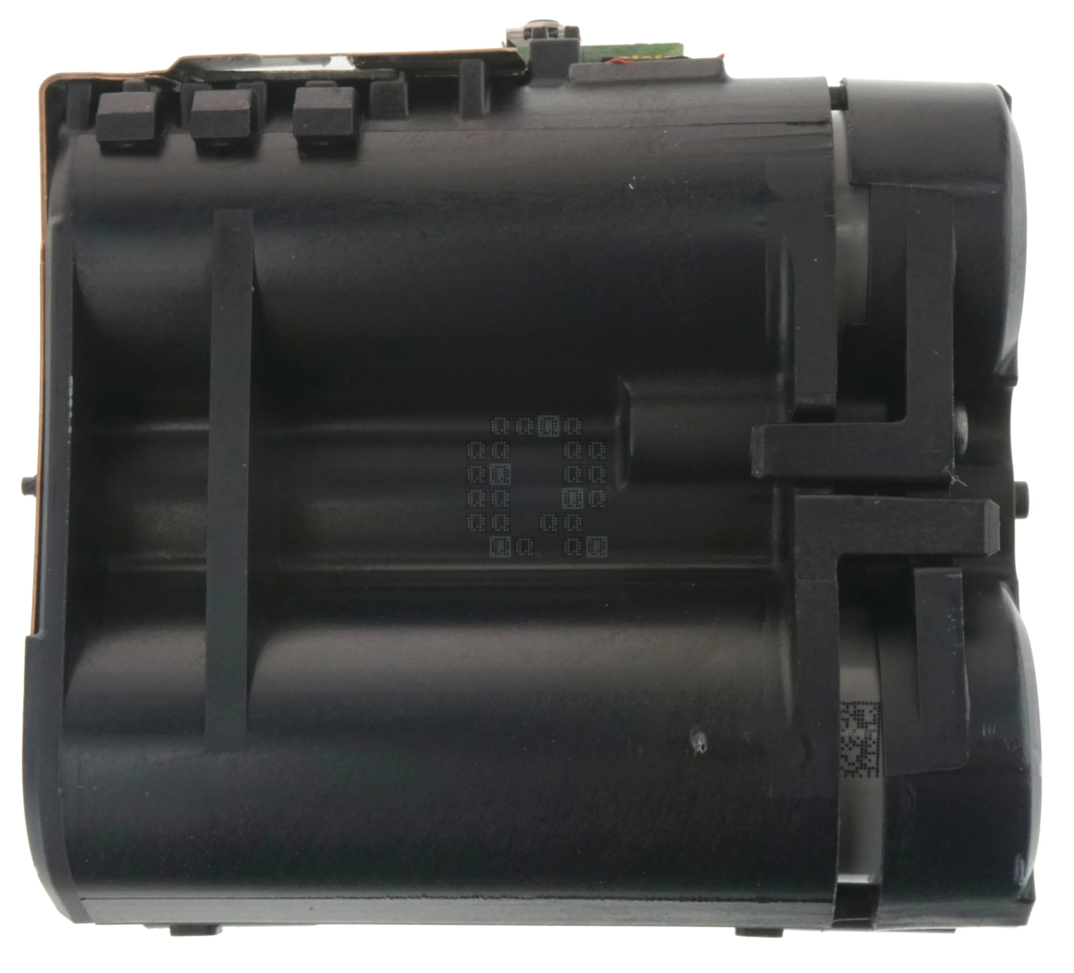
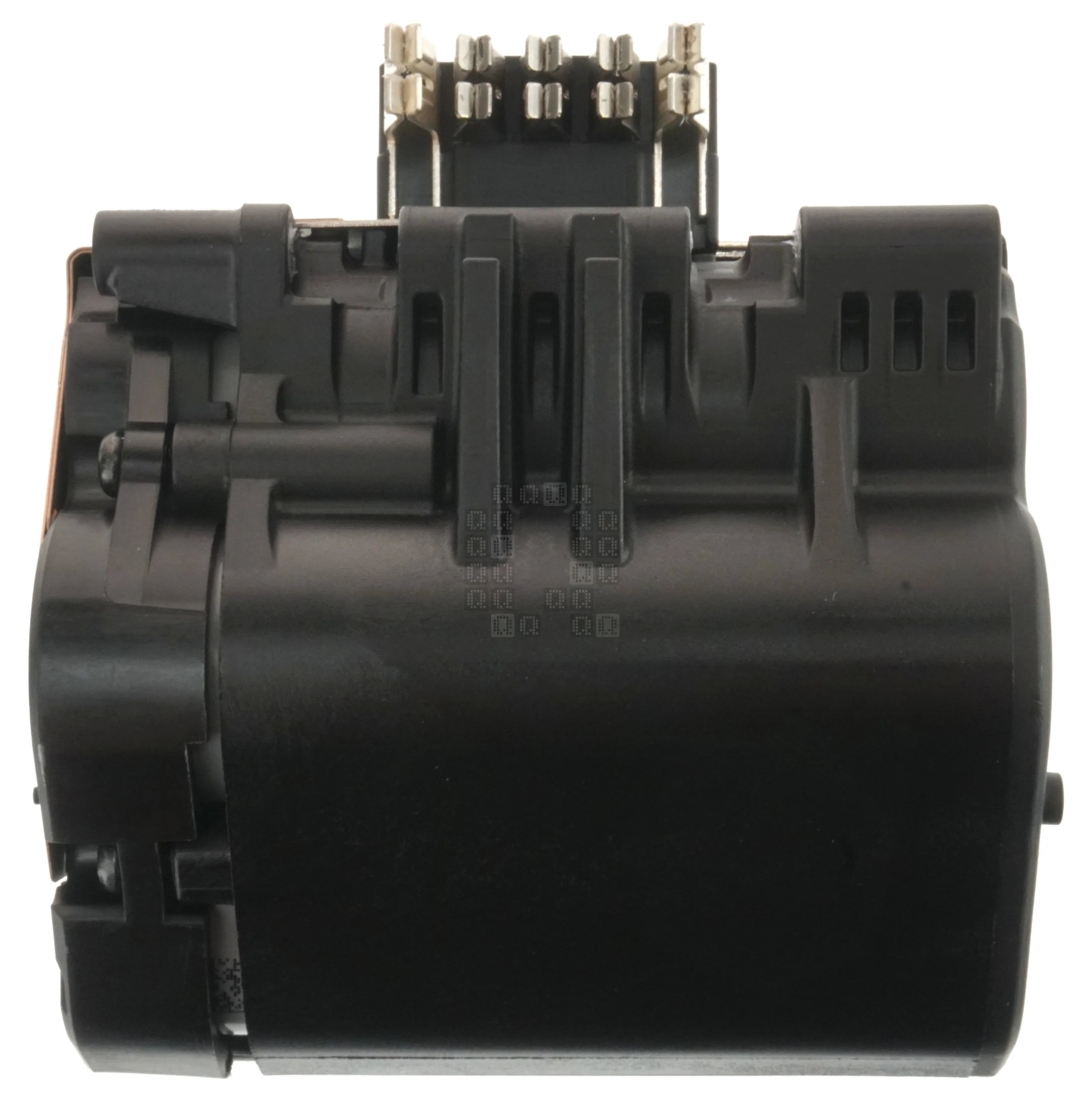
These are a couple images of the outside of the battery housing. Unfortunately, I was not able to see any of the cell markings to find a brand, cell type or capacity. The cells themselves seem pretty closed off, although they do have spacing around them to allow for airflow. Airflow appears to come in the ends of the cells / top of the pack and exit through the center bottom.
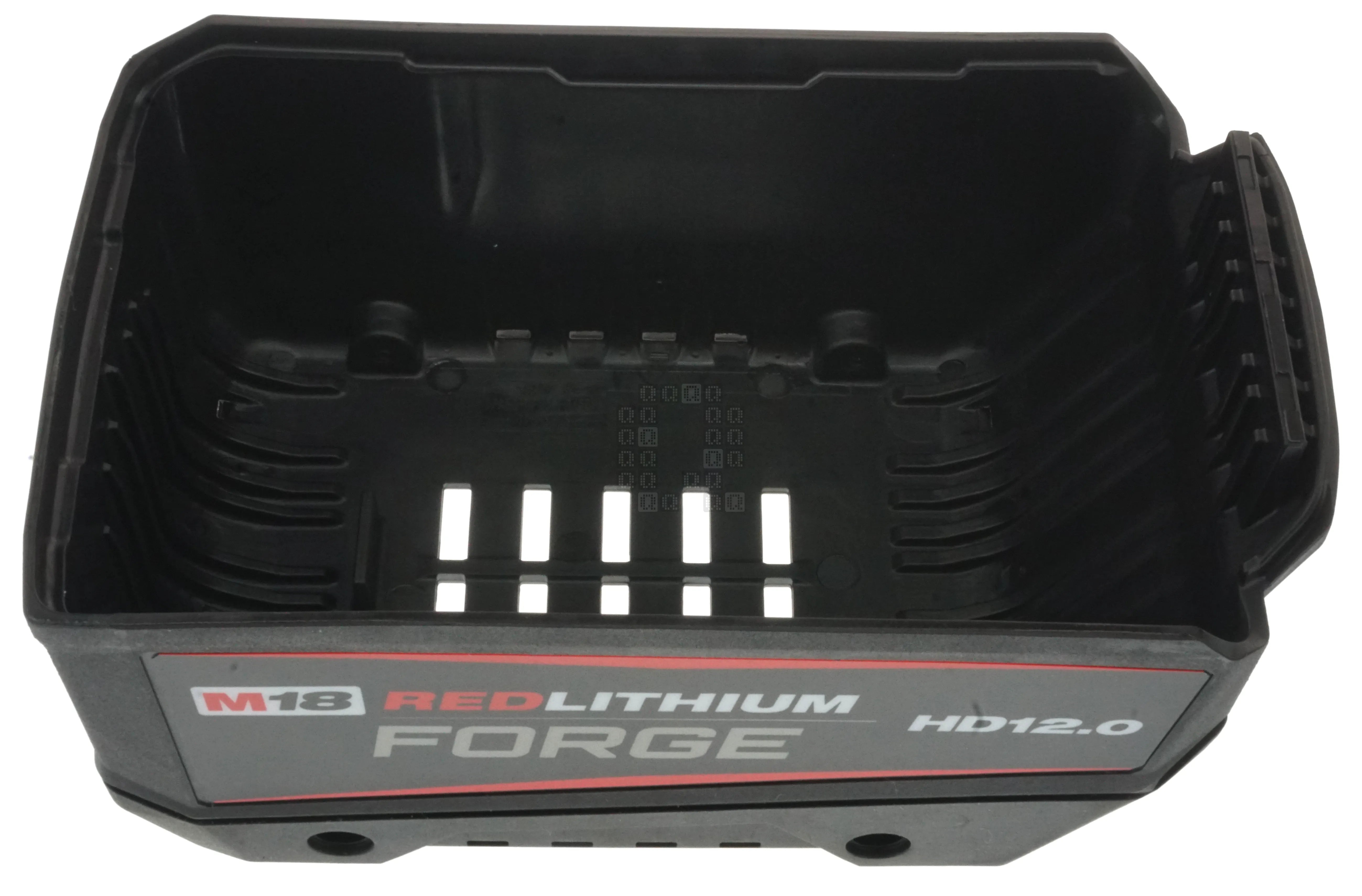
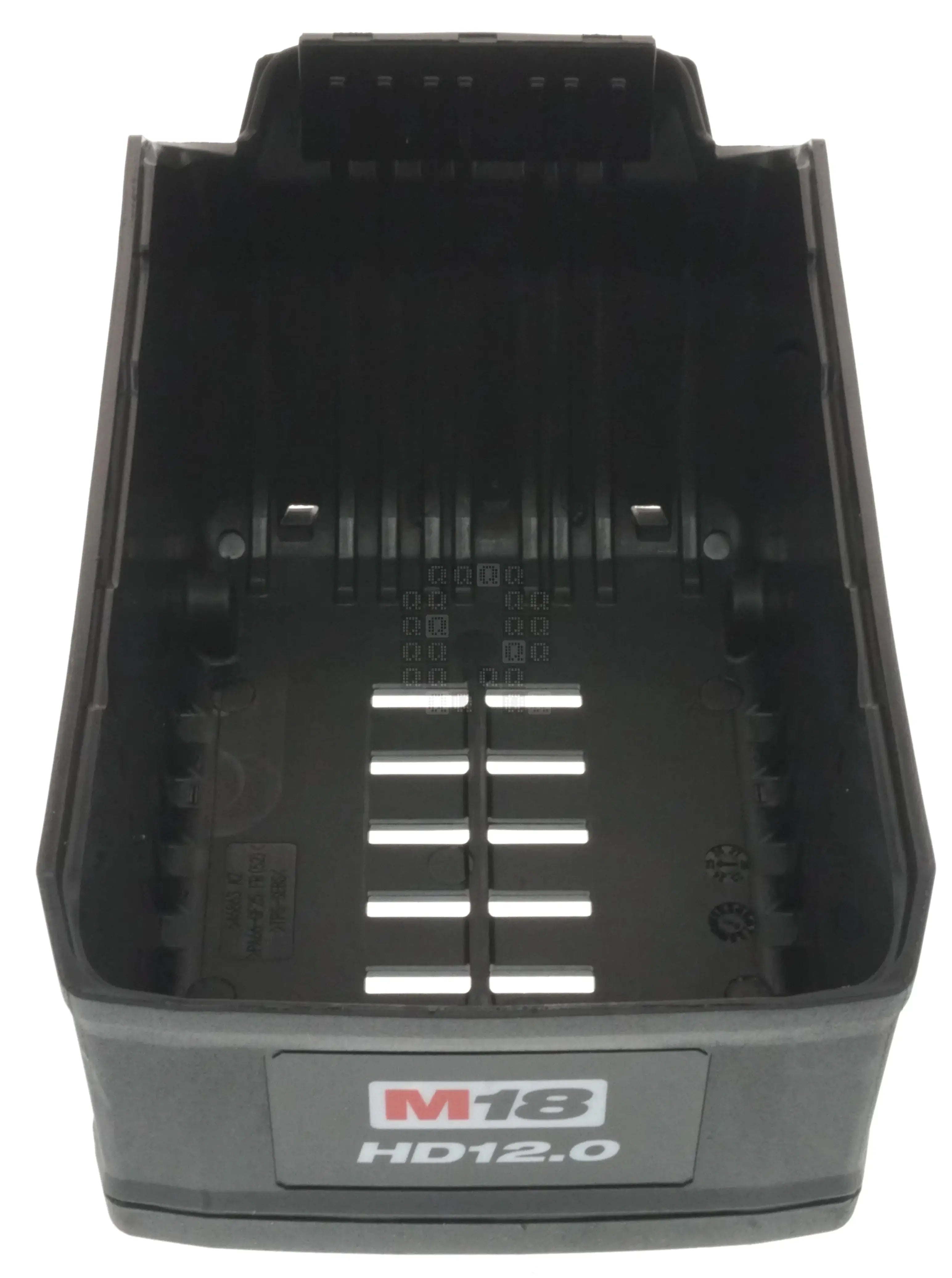
I'll end with 2 images of the bottom inside cover. Nothing overly interesting, but didn't want to miss a major piece.
Conclusion: Looks like the newest version of the same design with slightly larger cells. A couple things I missed - I don't see any liquid exposeure indicators - I assume they expect the battery internals to be exposed to liquids throughout its life. I'm also only seeing a light waterproofing on the circuit board - and I mean light. Unless there is something I'm missing, I'd really not suggest dunking these battery packs in any sort of liquids. Guess we'll see how well they hold up in a couple years... Anyway, hope you enjoyed a small exploration of my newest battery.