
Please Note: Clicking on an image will take you to a higher resolution version of the image you clicked on.
2026-08-08: Got another interesting repair that has stretched out way too long. It annoyed me a bit. So, I'm going to write this up so others can repair their equipment. I got a control panel for a Robinair CoolTech 34700Z Recovery/Recyling Unit. I was told it simply had a dead LCD. I confirmed that the LCD had power and was getting signals. I then ordered the first replacement LCD. And everything went downhill from there...
Overview of the problem:
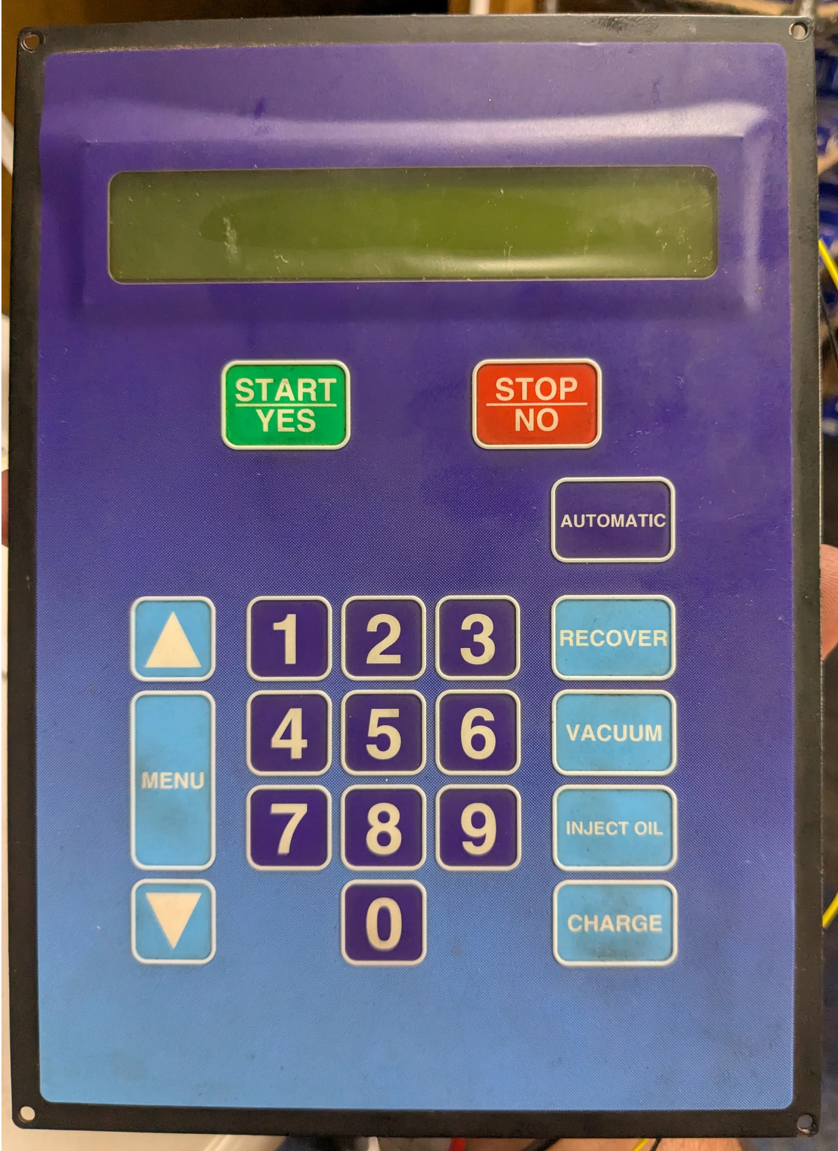
Front Control Panel / User Interface. Yes, this LCD is dead...even with power. The relays, they go click and the beeper goes beep (loudly)
|
|
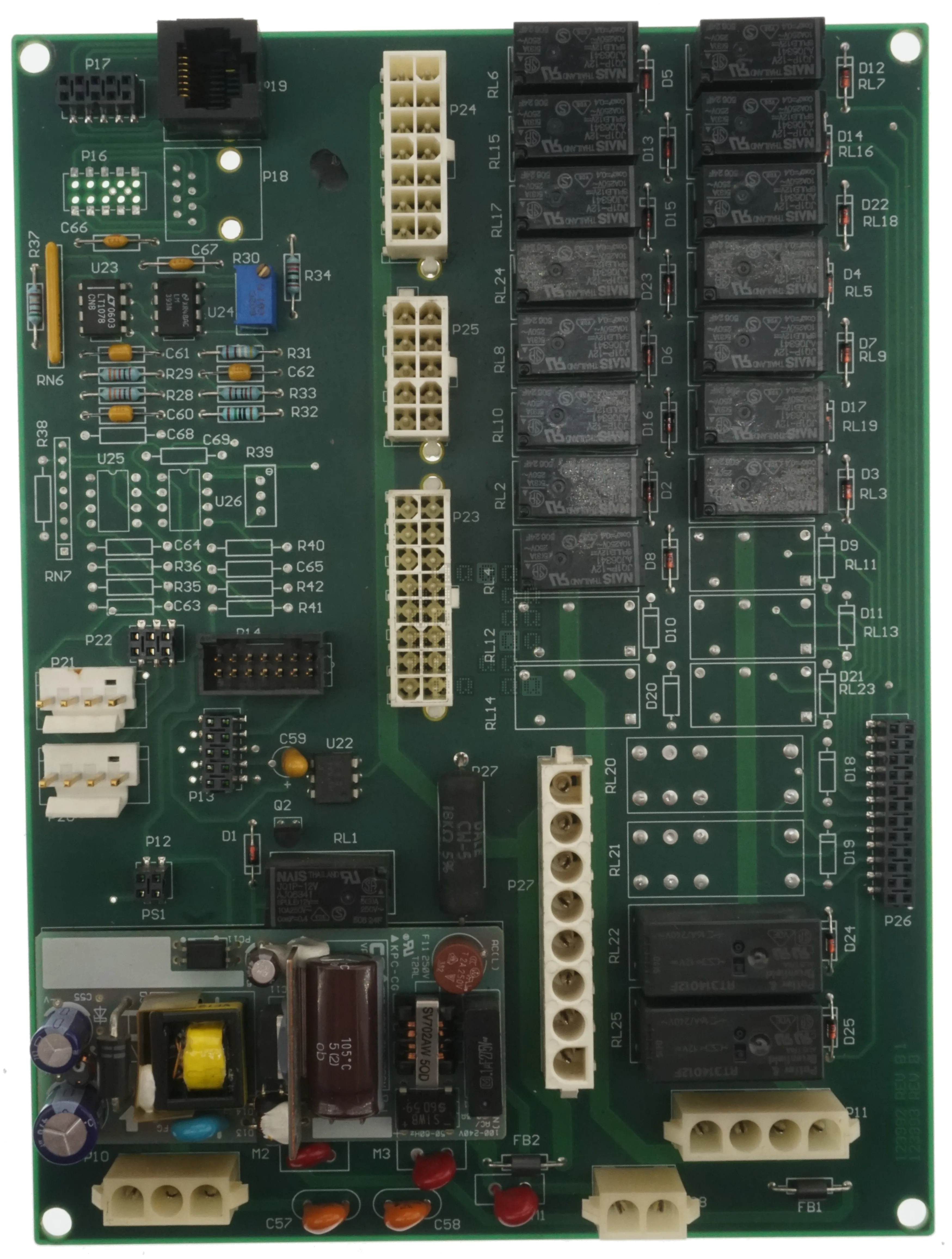
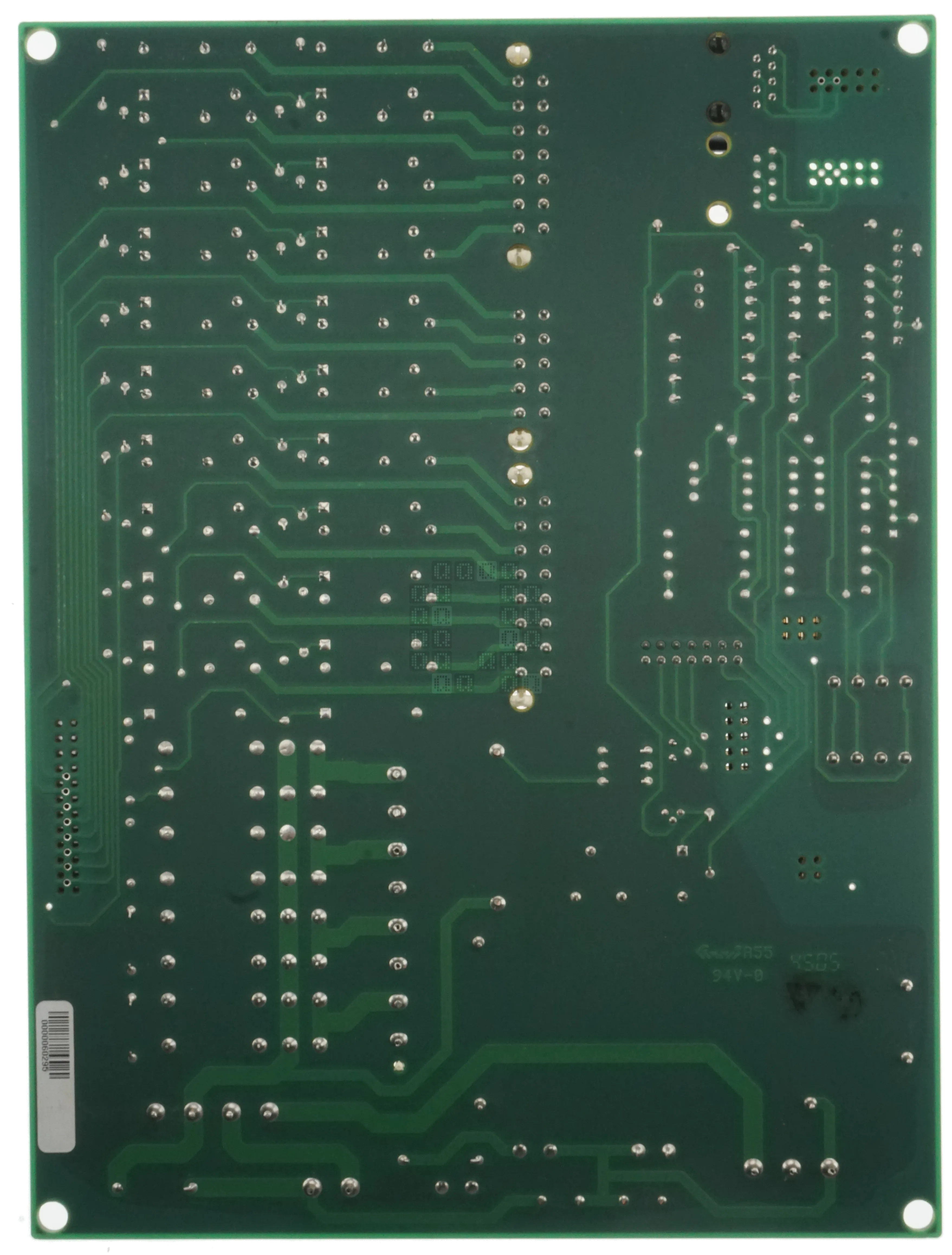
Front and Back of the Control Board. There is a serial number sticker on the back: 0000060295. On the front there are two model numbers: 123992 Rev B1 and 123993 Rev B. To get this board powered, you will need 3 sets of jumpers: P11 Pins 1 & 2 (Circuit breaker), P11 Pins 3 & 4 (Circuit breaker) and P28 Pins 1 & 2 (High Pressure Switch). Then input 120VAC on P10 Pins 2 & 3.
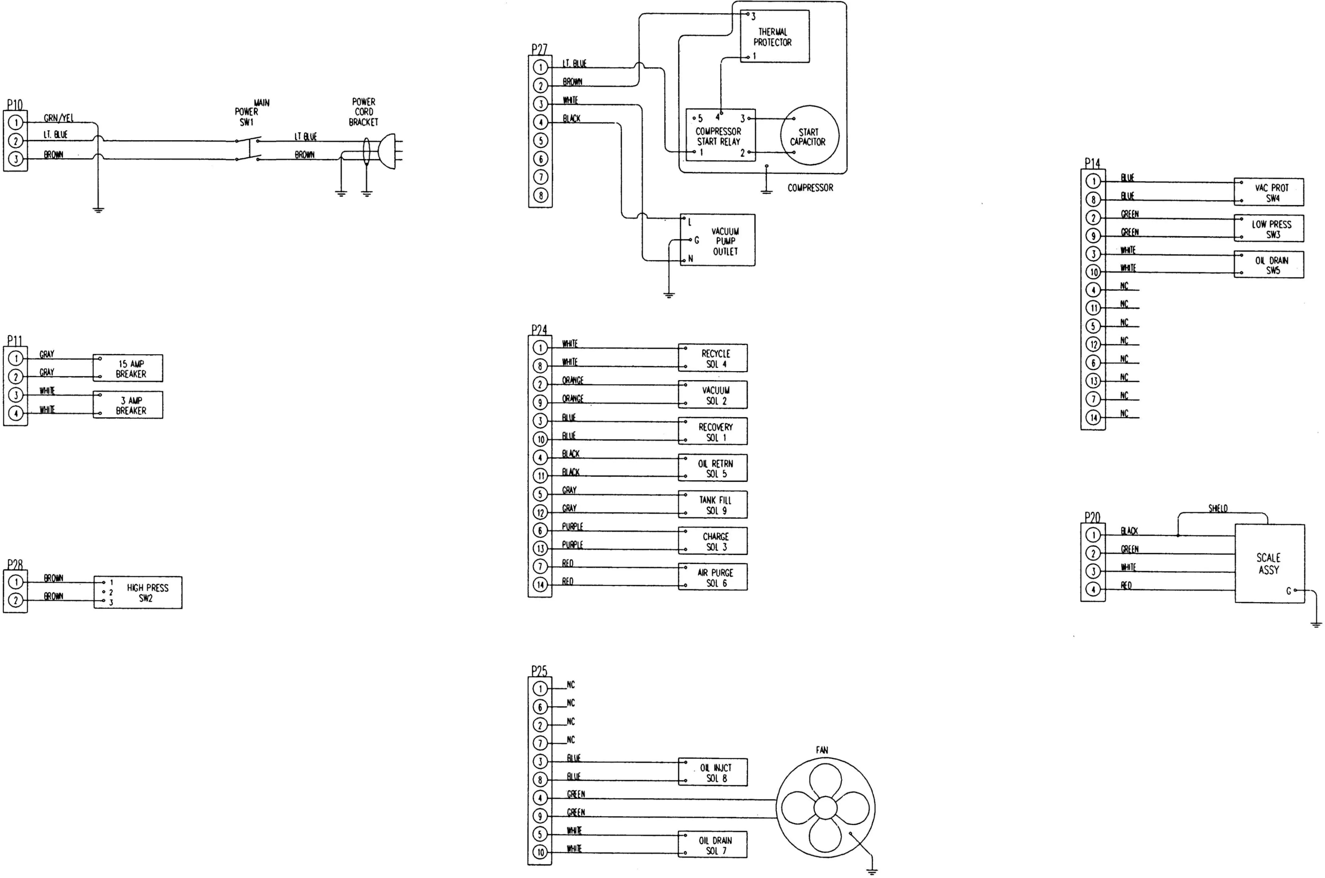
Electrical diagram for the 34700-2K/17700-2K. Even though this machine was labeled as a 34700Z, the diagrams in the manual for the 34700Z do not match this machine.
|
|
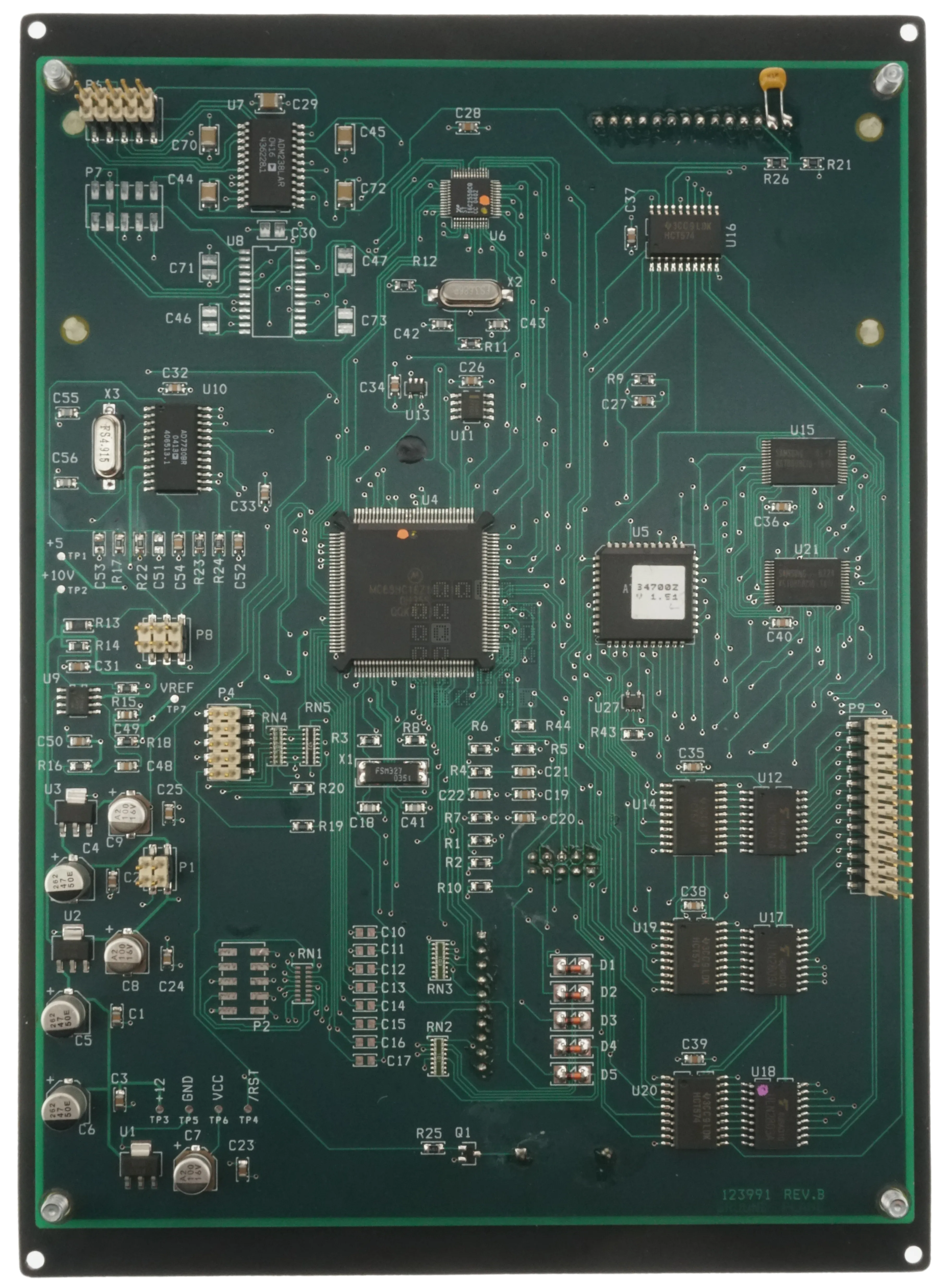
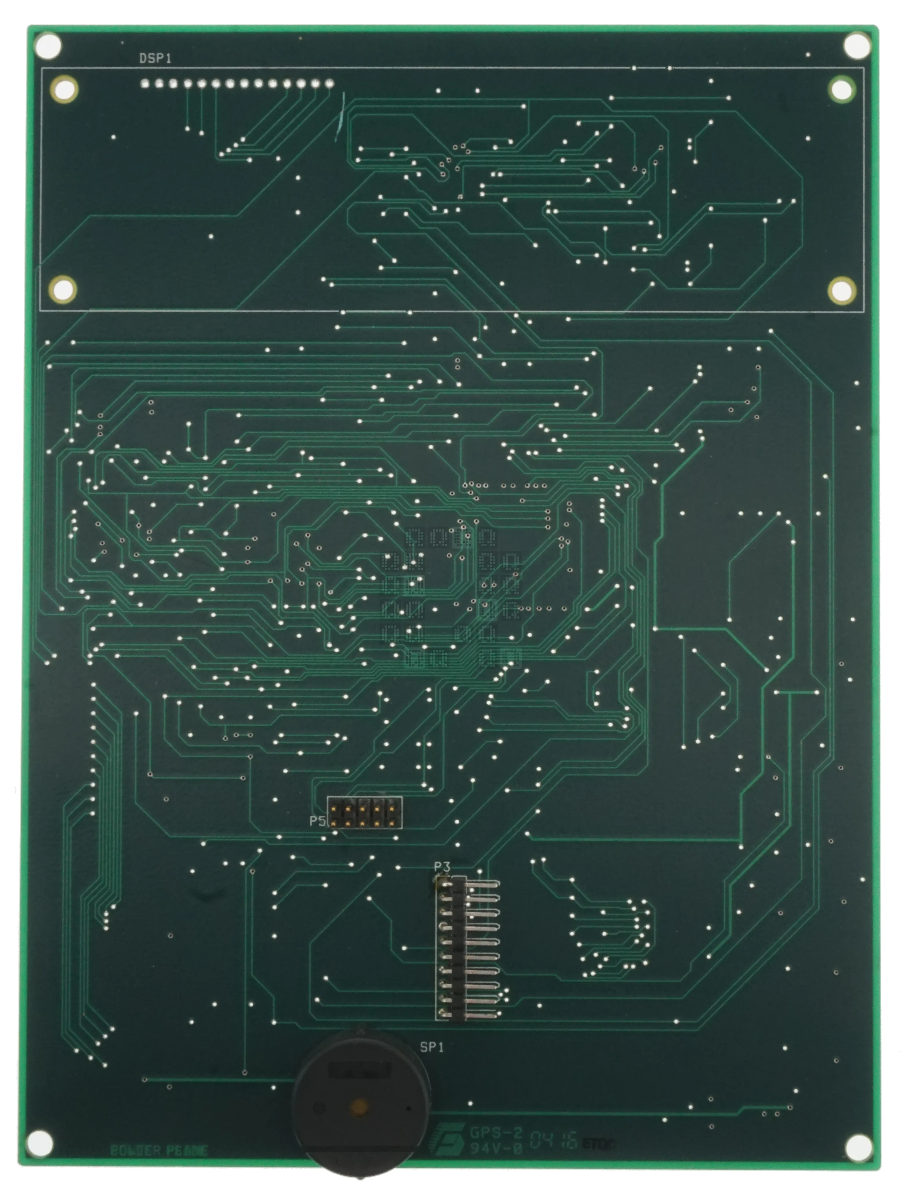
And this is the front and back of the CPU Board. This particular board is marked 123991 Rev B. Underneath this is a faint 'Ground Plane' note on the internal copper layer. I've removed the LCD on the back side of the circuit board.
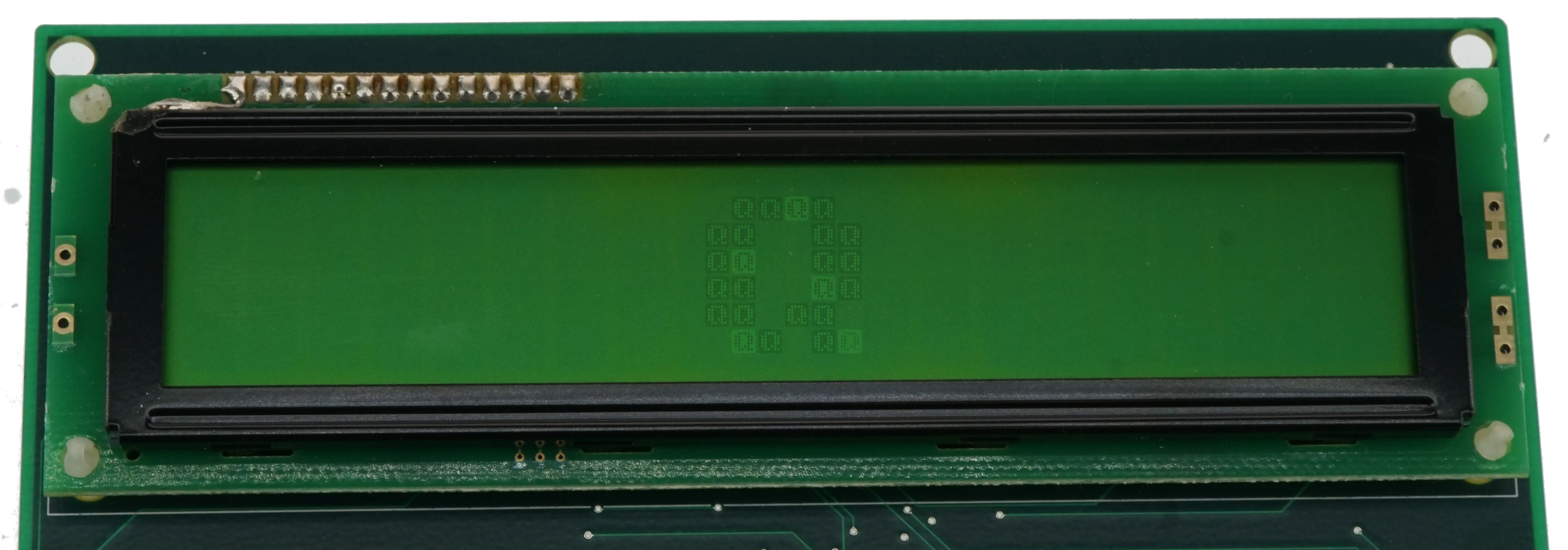
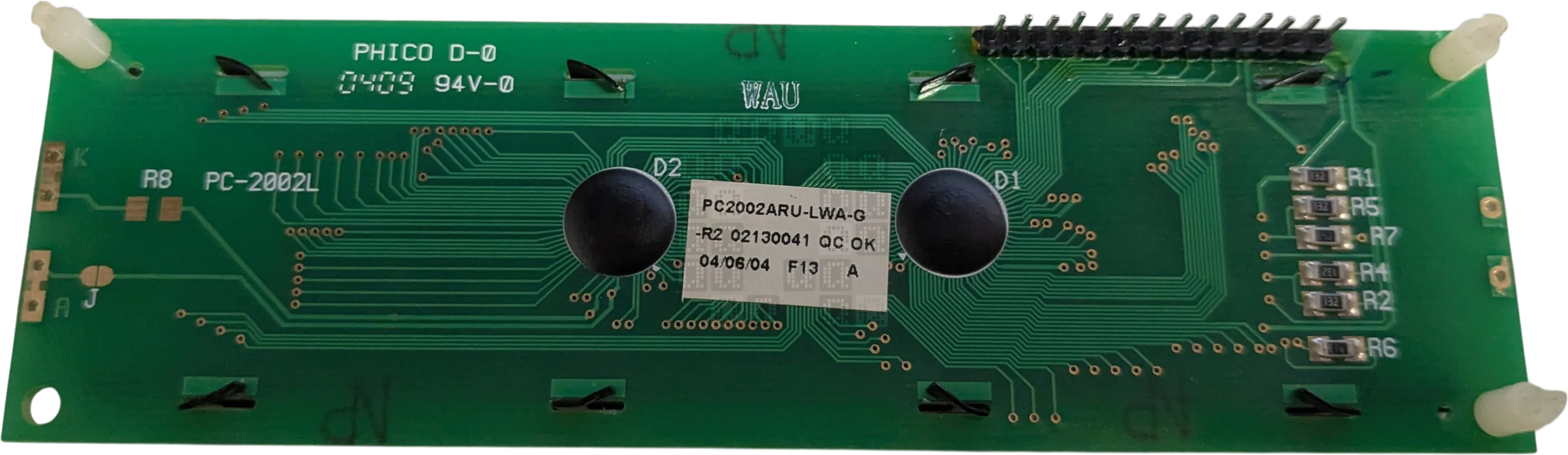
And this is the offending LCD. It is labeled 'PC2002ARU-LWA-G-R2' and was made in 04/06/2004. Circuit board measured 43x146mm. Lets break down the numbering a little:
- P - Powertip Products
- C - Character Type
- 20 - Characters per line
- 02 - Lines
- A - without backlight
- R - Standard - Through hole, cable connector and etc
- U - STN Positive Yellow-Green
- L - series number
- W - SITRONIX LSI
- A - Reflective polarizer, 6:00 Viewing, normal temp
- R2 - Special Code
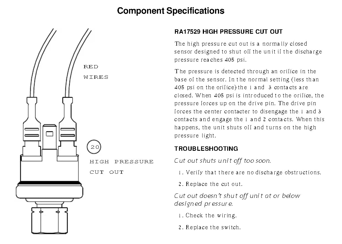
High Pressure Safety Switch (mentioned below)
Lets glance at the wiring for the screen too; I traced this out because at first I thought the signal was being blocked by a defective U16 (74HCT574). It turned out that I had not bypassed the high pressure safety switch (jumper P28 to mimic normally closed switch) and the smart little CPU had just blocked all the outputs (You'll notice U10, U14, U19 & U20 all share the same output enable line which runs directly back to the CPU)
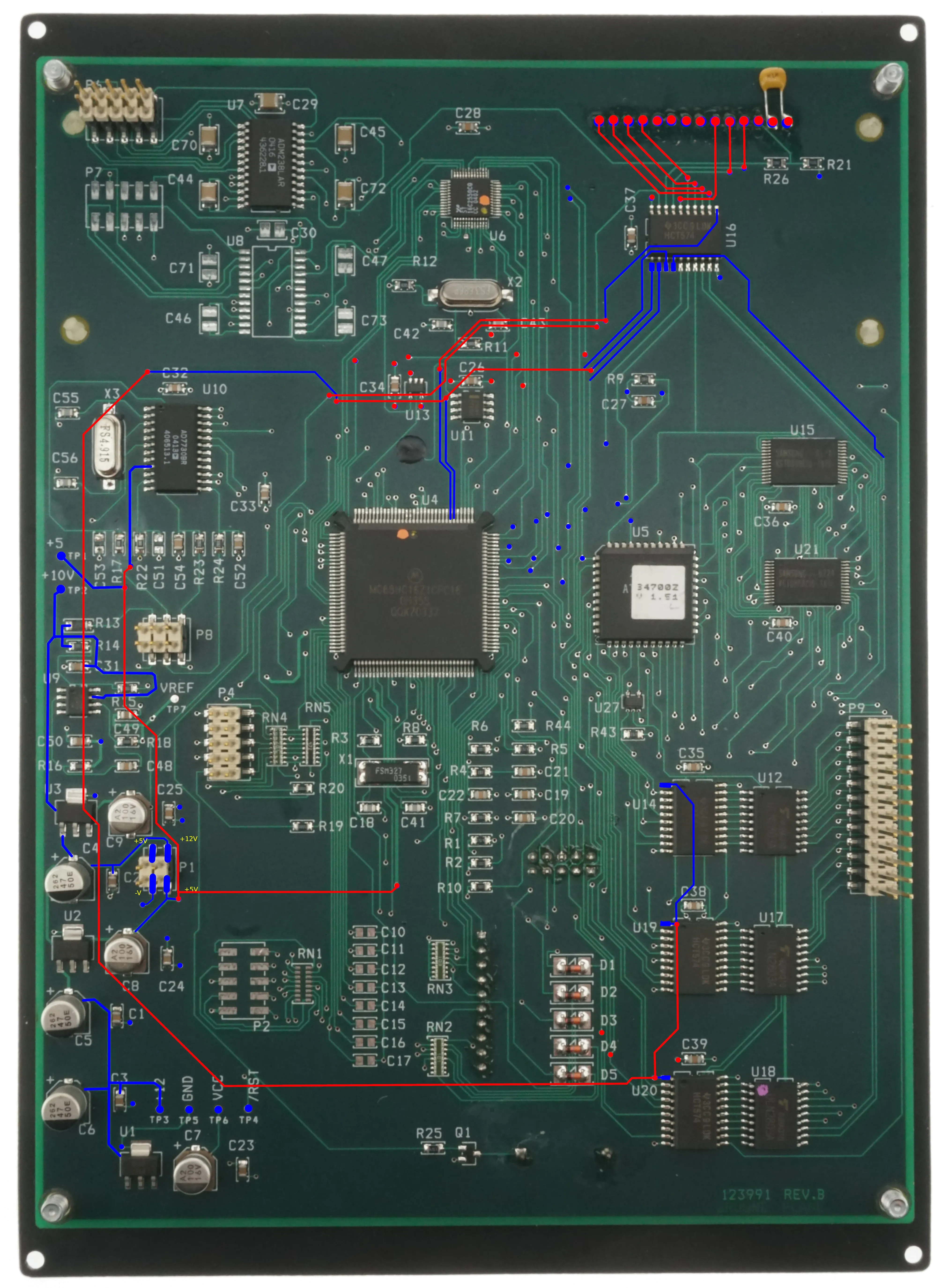
So this is the pinout for the LCD; we have a total of 14 pins.
- 1 - Ground
- 2 - +5VDC
- 3 - Contrast (Set by R26/21 Voltage Divider Resistors)
- 4 - RS (Command Register when Low, Data register when high)
- 5 - R/W (Low to Write, High to Read) This input was always low in my testing*
- 6 - E (Enable) Reads data on high to low transition
- 7-10 - Not Connected (Grounded)
- 11 - DB4
- 12 - DB5
- 13 - DB6
- 14 - DB7
* Keep in mind all data is passing through a one way 74HCT574 D-Type Flip-Flop. There is no way to read data from the LCD to the CPU.
This LCD is operating in 4-bit mode. There is a double e-pulse to load upper 4 bits and then the lower 4 bits. Also keep in mind that this is connected to a Motorola MC68HC16Z1CFC16 processor. Not all LCDs are made the same - we need one that supports 6800 mode and not just 8080 mode.
Unfortunately, this is where I ran into most of my annoying problems. There are plenty of LCDs out there with chipsets that support 6800 mode as well as 8080 mode. Datasheets will even have the correct pin labels for 6800 mode, but alas, they run in 8080 mode because the LCD manufacturer failed to bring out the pin required to select the 6800 mode (or they implemented it as a register bit that this circuit board will not flip because it was not programmed to do so). We won't mention here how long it took to check each display to see if it would work...
Solution to the problem:
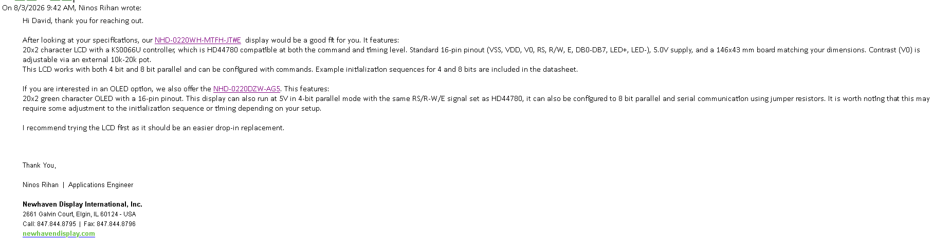
I do want to mention (and link to) Nehaven Display. They are the only company (out of 4) that responded and came back with a display that met my requirements. (Thank you, Ninos Rihan!) I'm going to link to both displays mentioned in the email: NHD-0220WH-MTFH-JT#E and NHD-0220DZW-AG5 After reading the datasheets, I chose to go with the NHD-0220DZW-AG5 20x2 OLED Display, even though it was the incorrect size. (It has a jumper to switch between modes and is wired from factory for 6800 mode! - Exactly what I needed!)
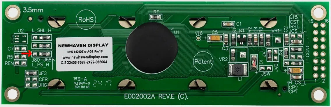
I neglected to take a clear image of the back of the new LCD, so this is a manufacturer photo with the jumper in question marked with a red arrow.
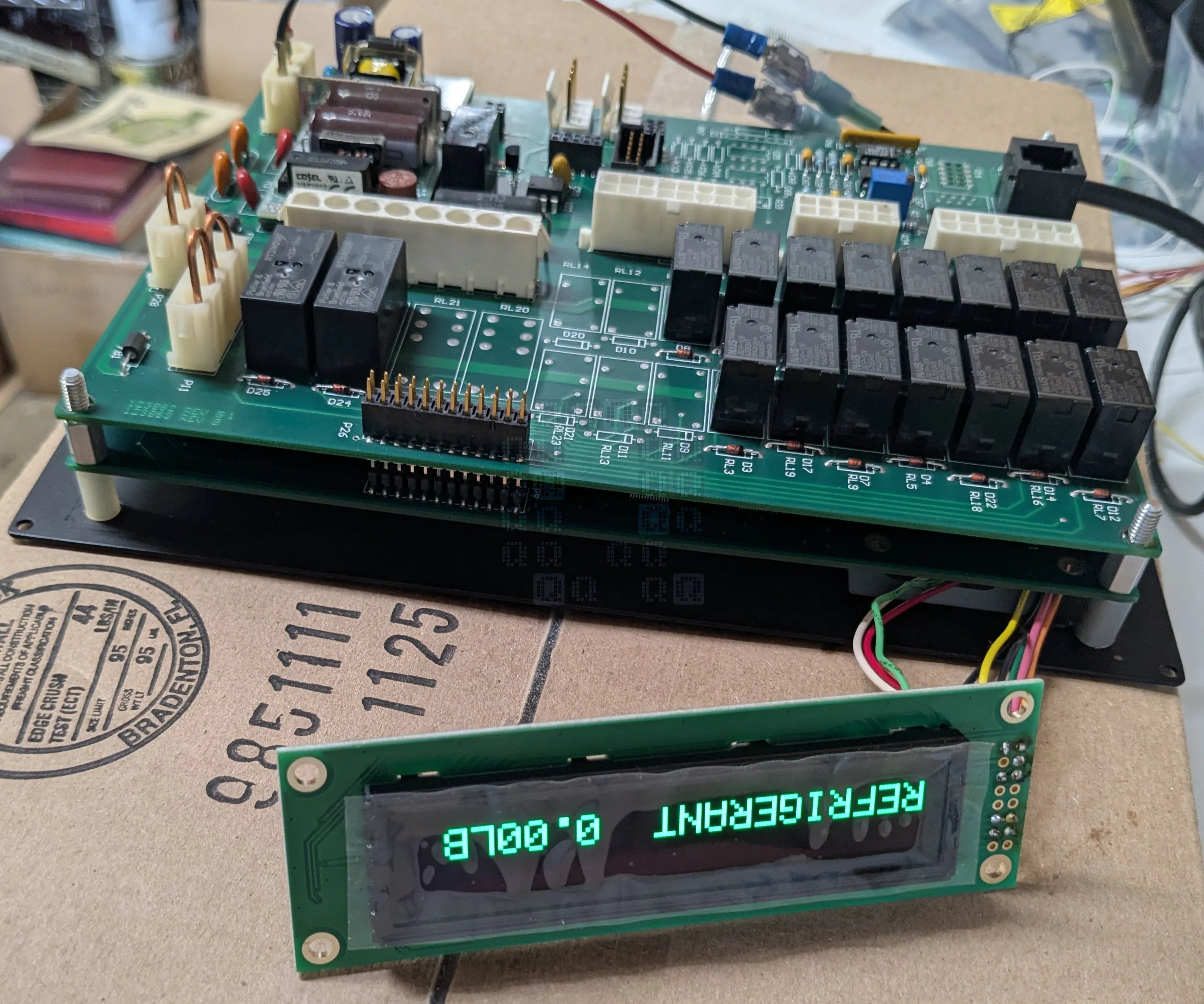
First image of a working LCD. Please don't criticize my jumpers. (if you said 'huh? what jumpers', there's nothing to see here...) To make this work, you will need to solder a couple jumper wires - I made mine about 6 inches long - I'd go with 4 inches or so next time. You'll need to solder the wires listed in the table below - pin numbers stay the same, but pin locations are different on the display vs the circuit board - pay attention to the labels on the boards and you should be fine. You'll need a total of 9 wires.
- 1 - Ground
- 2 - +5VDC
- 4 - RS
- 5 - R/W (Read/Write)
- 6 - E (Enable)
- 11 - DB4
- 12 - DB5
- 13 - DB6
- 14 - DB7
Once that is done (or maybe before that point), grab these 3d files and print them out on the nearest 3d Printer. (Print in your choice of materials - I used PA6-GF, but ABS would probably work too). This ZIP file contains a faceplace, standoff and screw bushing (just in case one was missing when you disassembled your unit.) Glue the standoffs to the back of the LCD with the little stubby sticking in the screw holes. Then nestle the LCD inside the faceplate and mount the circuit board. If everything works right (and yours is like mine) the circuit board and front steel plate will hold the faceplace in place.
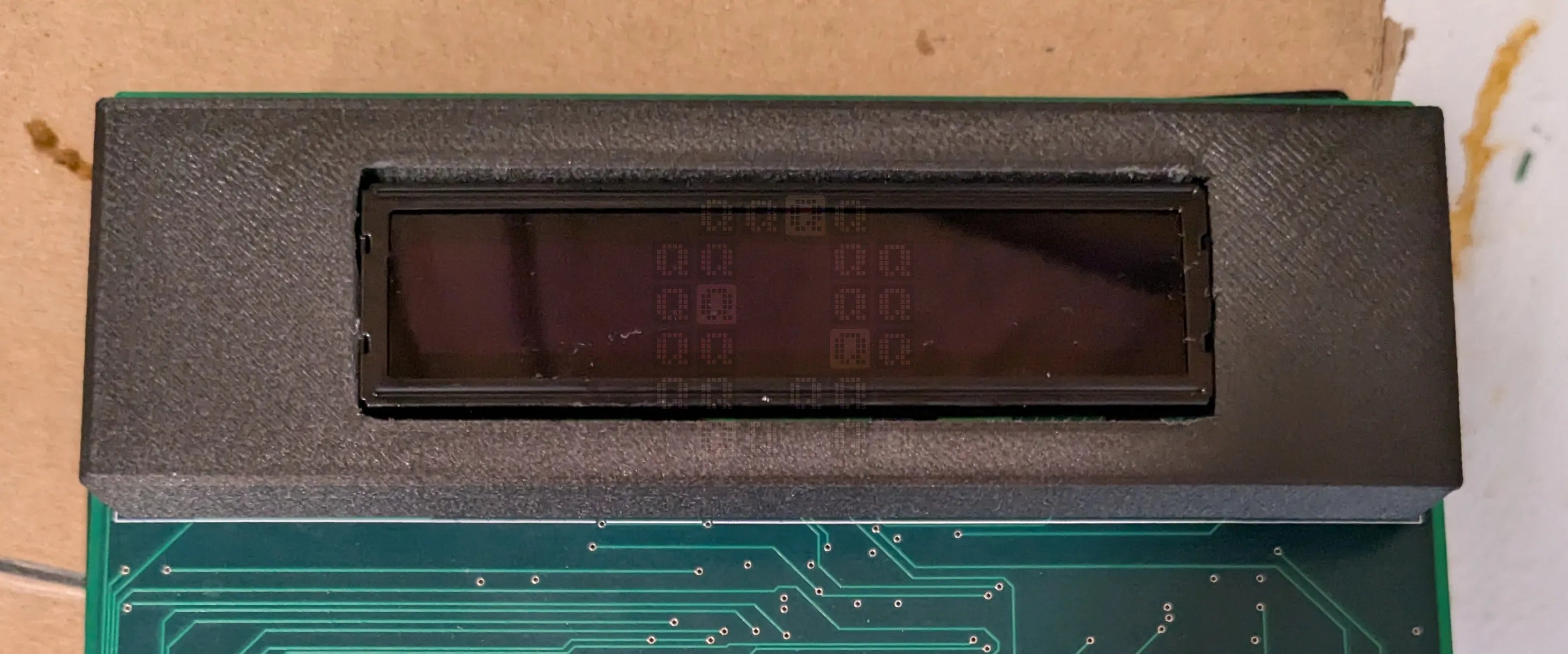
3d printed faceplate (this is my only image of it and it is my first attempt which had a slight dimensional issue caused by me misreading a marking on the drawing.)
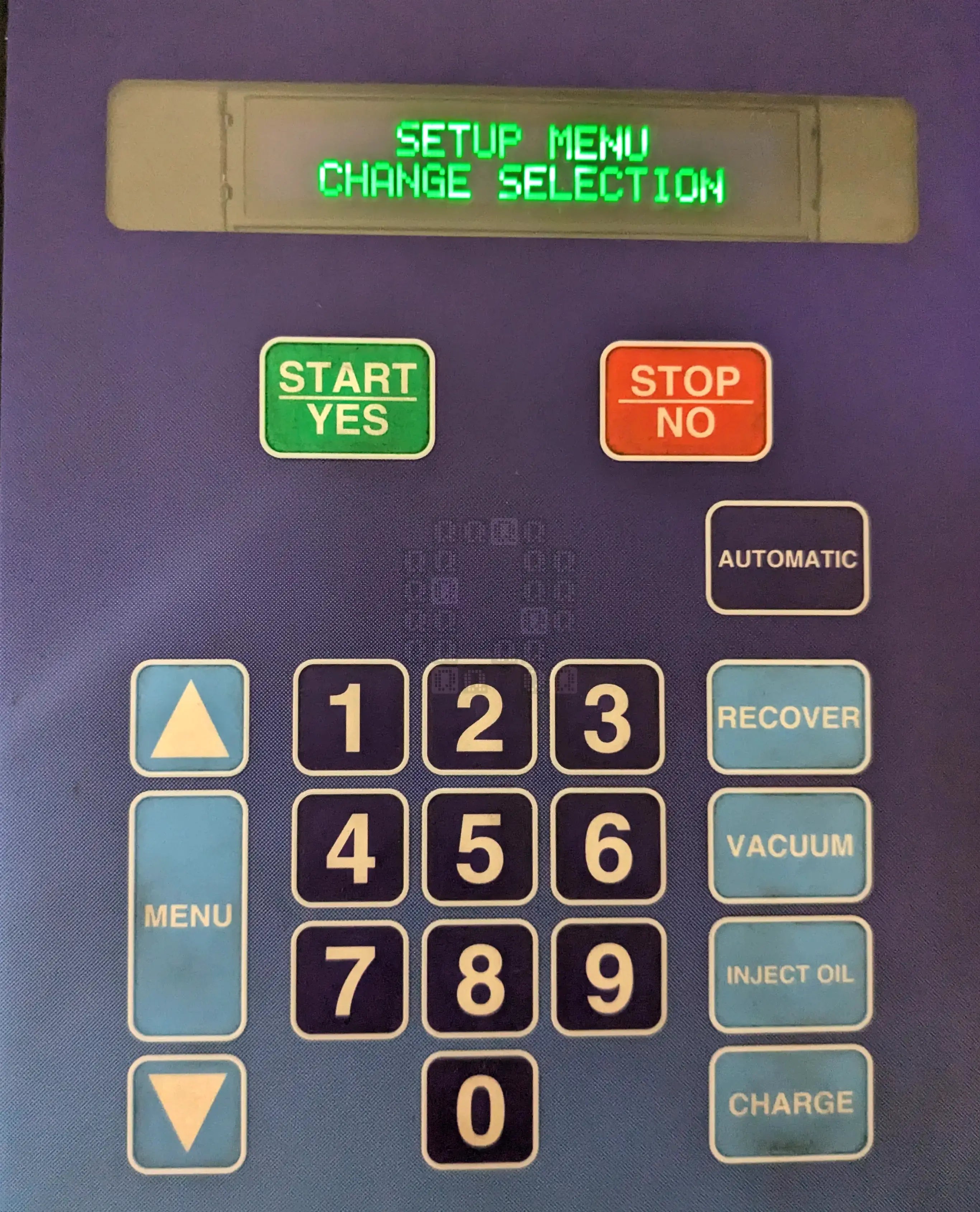
If everything goes well, you should be greeted by a lovely bright green oled display. Unless of course you opted to purchase the blue version (NHD-0220DZW-AB5) or the yellow version (NHD-0220DZW-AY5) to match other equipment or tools in your shop. (hey, I'm allowed to promote someone's products - especially someone that helped me out, right? And no, this is not paid in any way...)
Please don't be this guy...
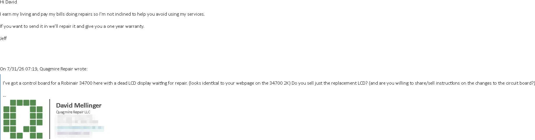
Please don't be like this guy. He seems to think an LCD replacement (and his labor for the repair) for this circuit board is worth $750-1000+shipping. He is one of the reasons I am posting this. I've redacted his information. I'm not inclined to advertise his business here, but I'm willing to give an un-honorable mention.
Datasheets:
Bosch/Robinair supplied an operator's manual. It is pretty much unreadable.
Newhaven NHD-0220DZW OLED Display Module Datasheet since I didn't reference it anywhere above.
Geekier Details
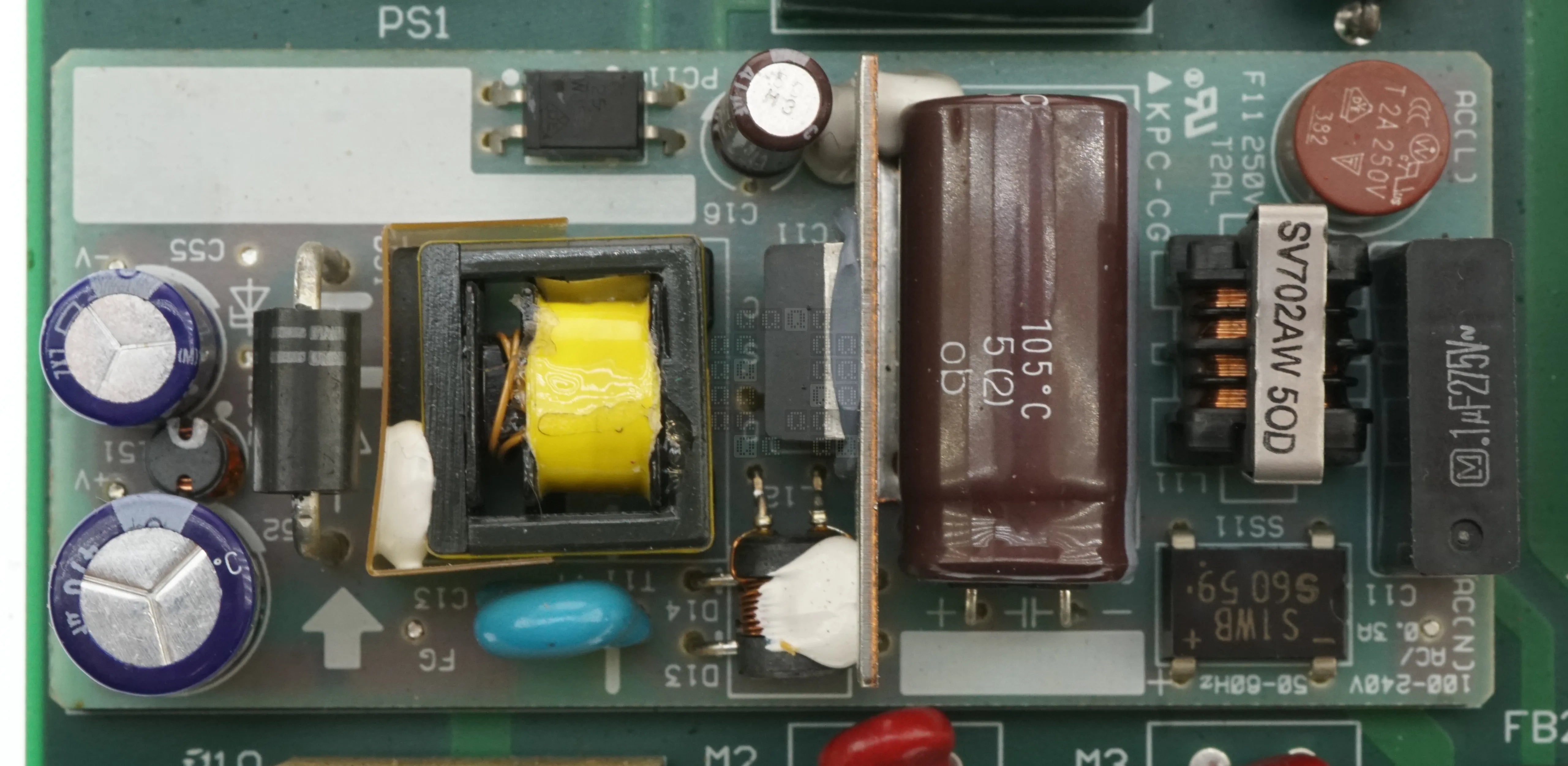
Lets start with the power supply; This here little add-on unit produces 12VDC/0.9 Amps on the V+ and V- pins. The FG terminal appears to be a ground. The power supply is marked 'Cosel VAF1012' on the input 0.1uF/275VAC box capacitor. There are a lot of surface mount components on the back. This power is used for the relay coils and is also sent down to the CPU board via the 4-Pin PS1 terminal. Clockwise starting at upper right is +12VDC, +5VDC (generated on CPU board), 0VDC (V-) and +5VDC.
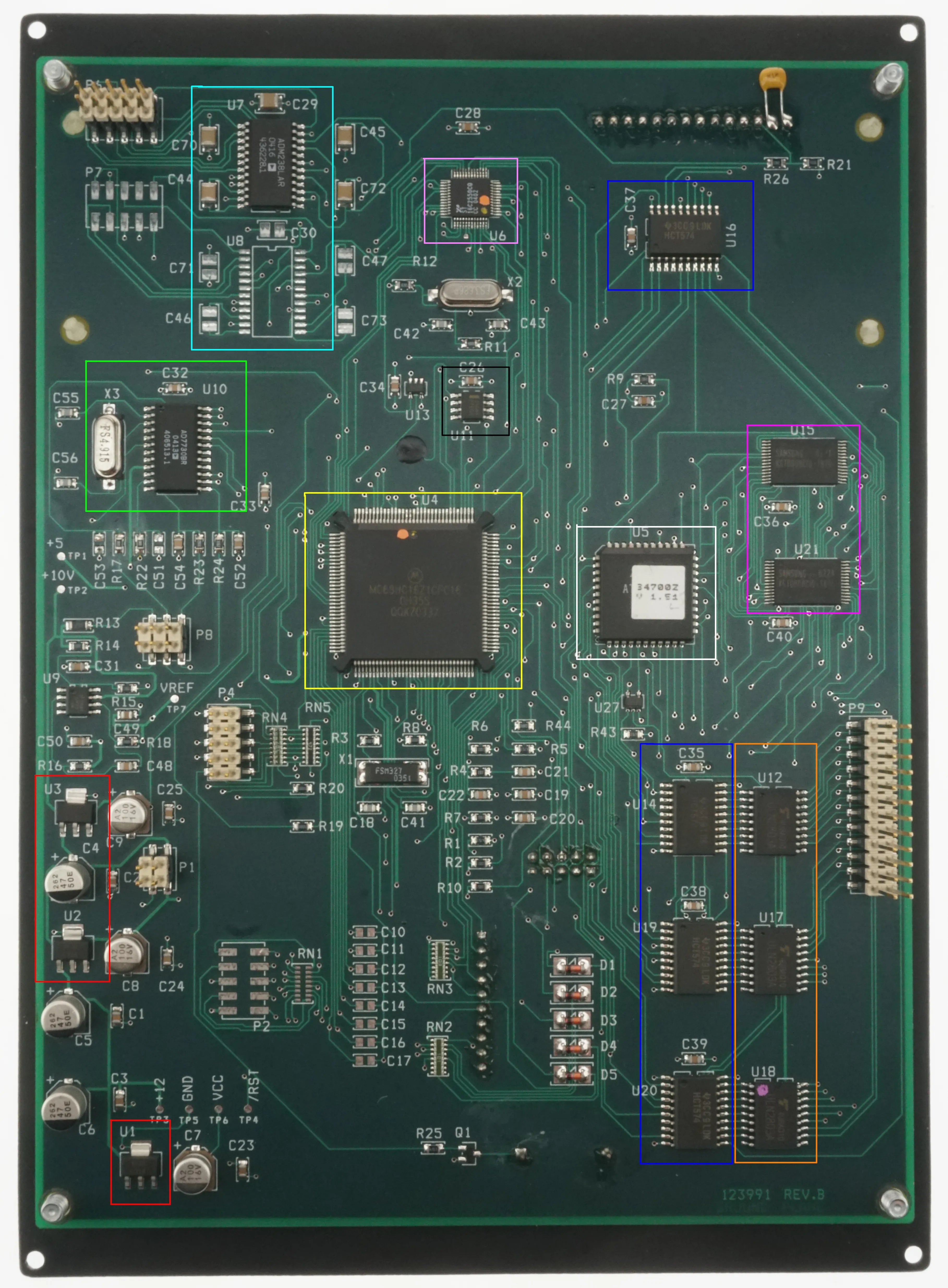
And here is where we get to do a quick overview of everything on the board - there's actually a lot happening here! This is a complete computer running here.
- RED (U1, U2 & U3)
- U1, U2 & U3 are voltage regulators - I did not trace them out, but there are at least one +5VDC rail and one +10VDC rail generated by these. U9 may also have been a voltage regulator (I neglected to mark this IC down.)
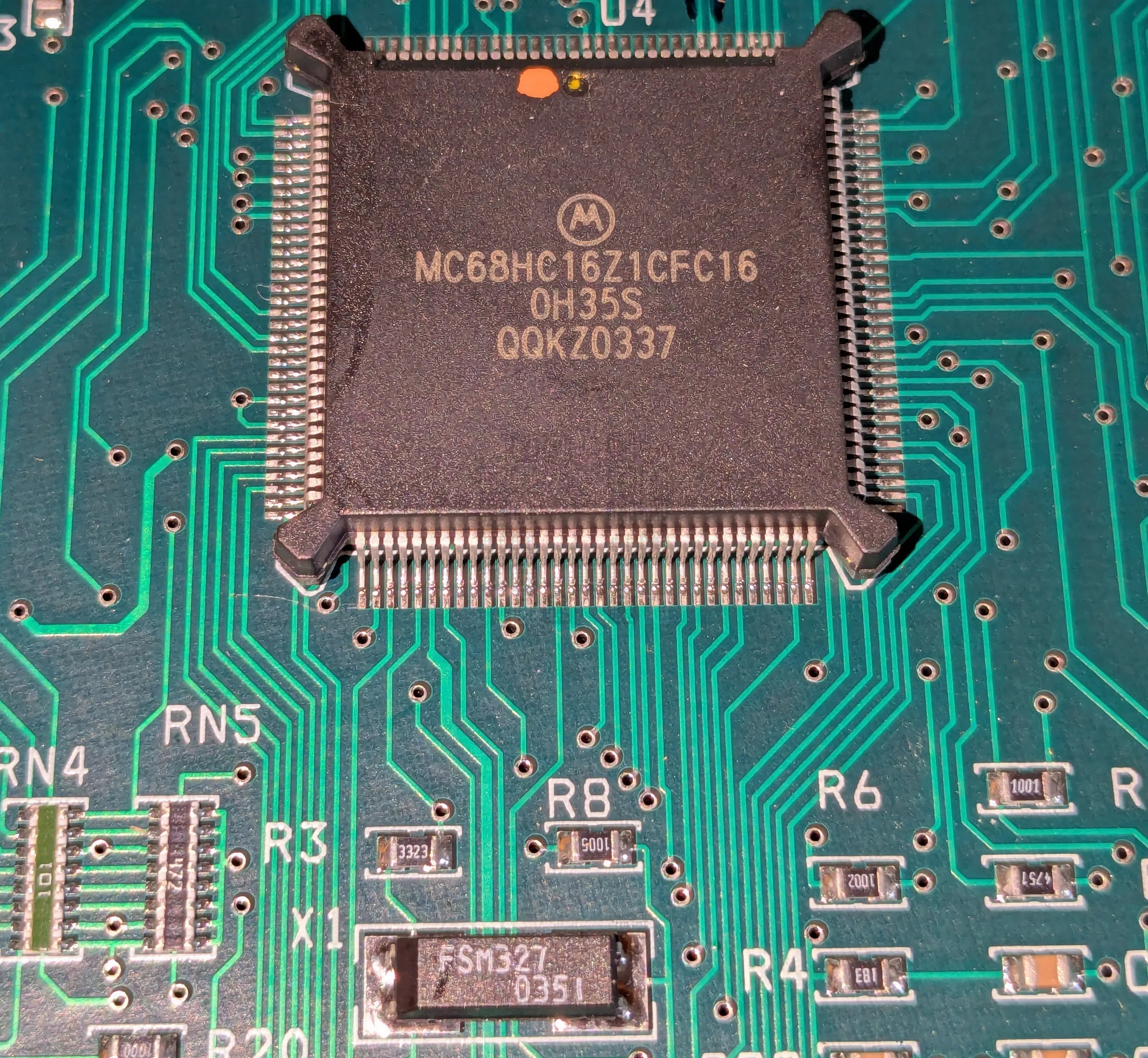
- YELLOW (U4)
-
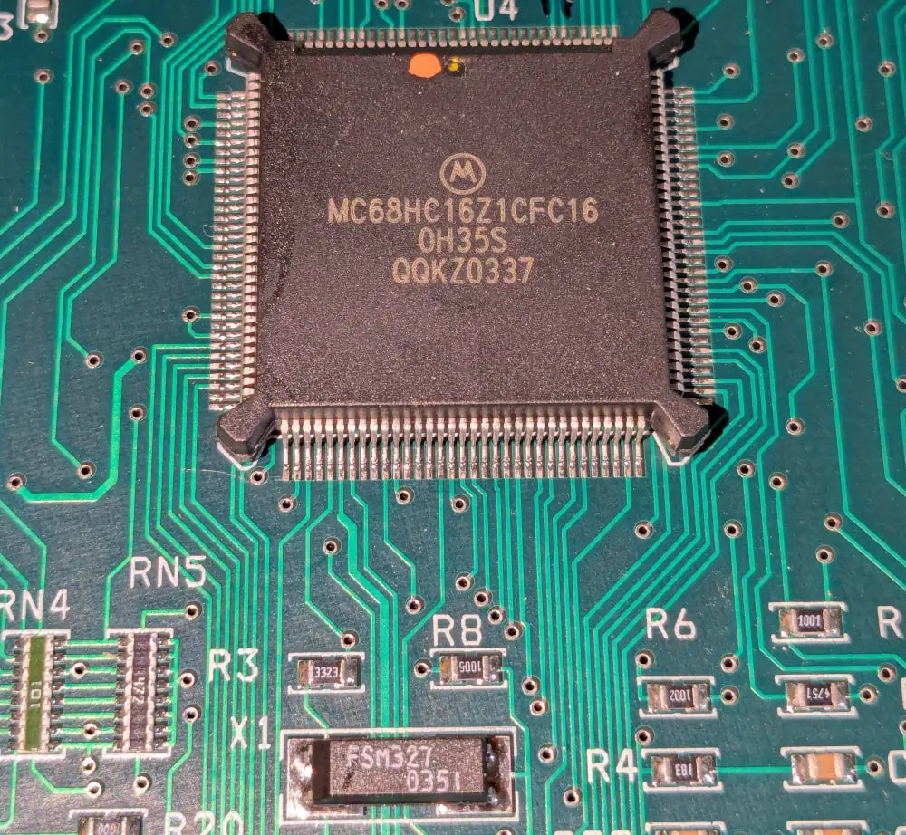
U4 is a Motorola MC68HC16Z1CFC16 Microcontroller. 16-Bit, up to 1KByte of SRAM. X1 (FSM327, below) is a 32.768KHz Crystal which the microcontroller uses to generate its internal system clock (probably 16.78MHz) Datasheet here. And no, I didn't dive into this except to read the specs and reference the pinout (page 358 - this is the 132 pin package, btw). - WHITE (U5)
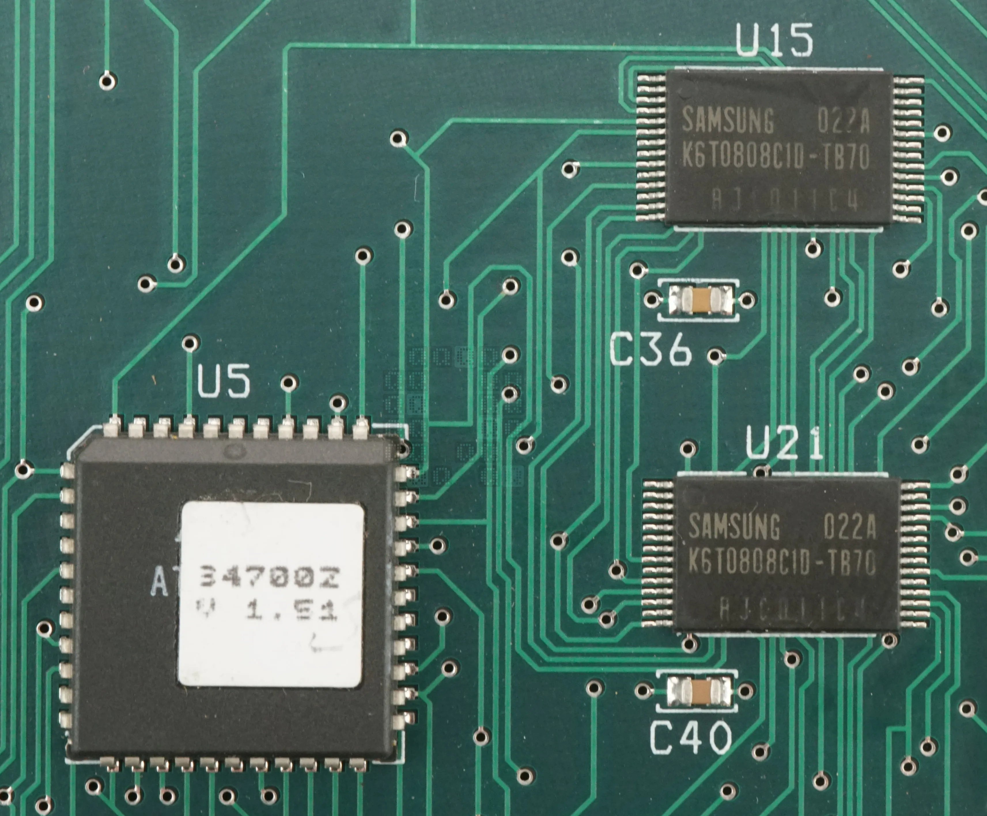
-
I assume U5 is the ROM - The sticker is marked 34700Z V1.51.I probably should have peeled the sticker just for curiosity.
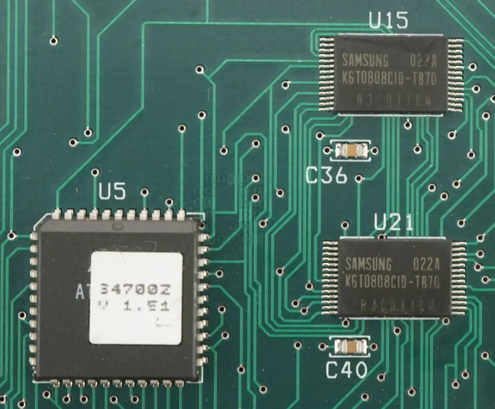
- MAGENTA (U15 & U21)
- Two Samsung K6T0808C1D-TB70. 32Kx8 bit 28-Pin 70ns LL_power, Commercial grade CMOS Static RAM (no datasheets found from the manufacturer, only 3rd party marked up ones) This is a roomy 64KBytes of RAM for this system!
- GREEN (U10)
- This is an Analog Devices AD7730BR Bridge Transducer ADC. Datasheet Here. The datasheet specifically mentions that this IC is designed for weigh-scale and pressure measurement applications. It takes two analog signals (AIN1/AIN2) and outputs them as a serial word. There are way more functions here than I will dive into. There are two headers P20 & P21 connected to this, but only P20 is mentioned in the manual. (Sorry, no closeup of this IC)
- CYAN (U7 & U8)
-
This IC is an Analog Devices CMOS RS-232 Driver/Receiver. Datasheet here. (This board has room for two of them). The connections to this board go to the P19 Jack, but I was unable to find out its purpose.
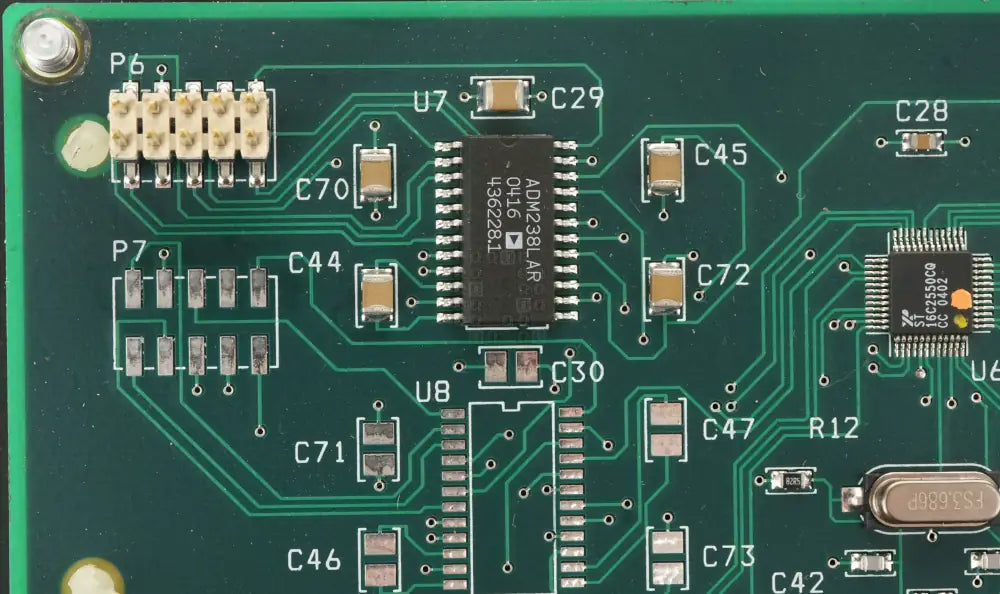
- PINK (U6)
- ST16C2550CQ Dual Asynchronous Receiver/Transmitter (UART) with a 16-byte FIFO. The crystal right below it (FS3.686P) is used for the baud rate generator, but not the internal operation of the IC.
- BLUE (U14, U16, U19 & U20)
-
74HCT574 Octal Edge-Triggered D-Type Flip-Flop with 3-State Outputs. Datasheet Here.
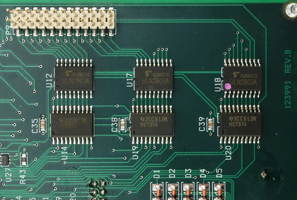
- ORANGE (U12, U17 & U18)
- ULN2803A 600mA Darlington Transistor Array with suppression diodes. A nice simple way to drive inductive loads, such as relays. Datasheet Here.
- BLACK (U11)
- This appears to be a 34064 Undervoltage Sensing Circuit. I had to look into this because the trace for pin 1 disappears into a black hard epoxy covered area. There's no explanation for it.
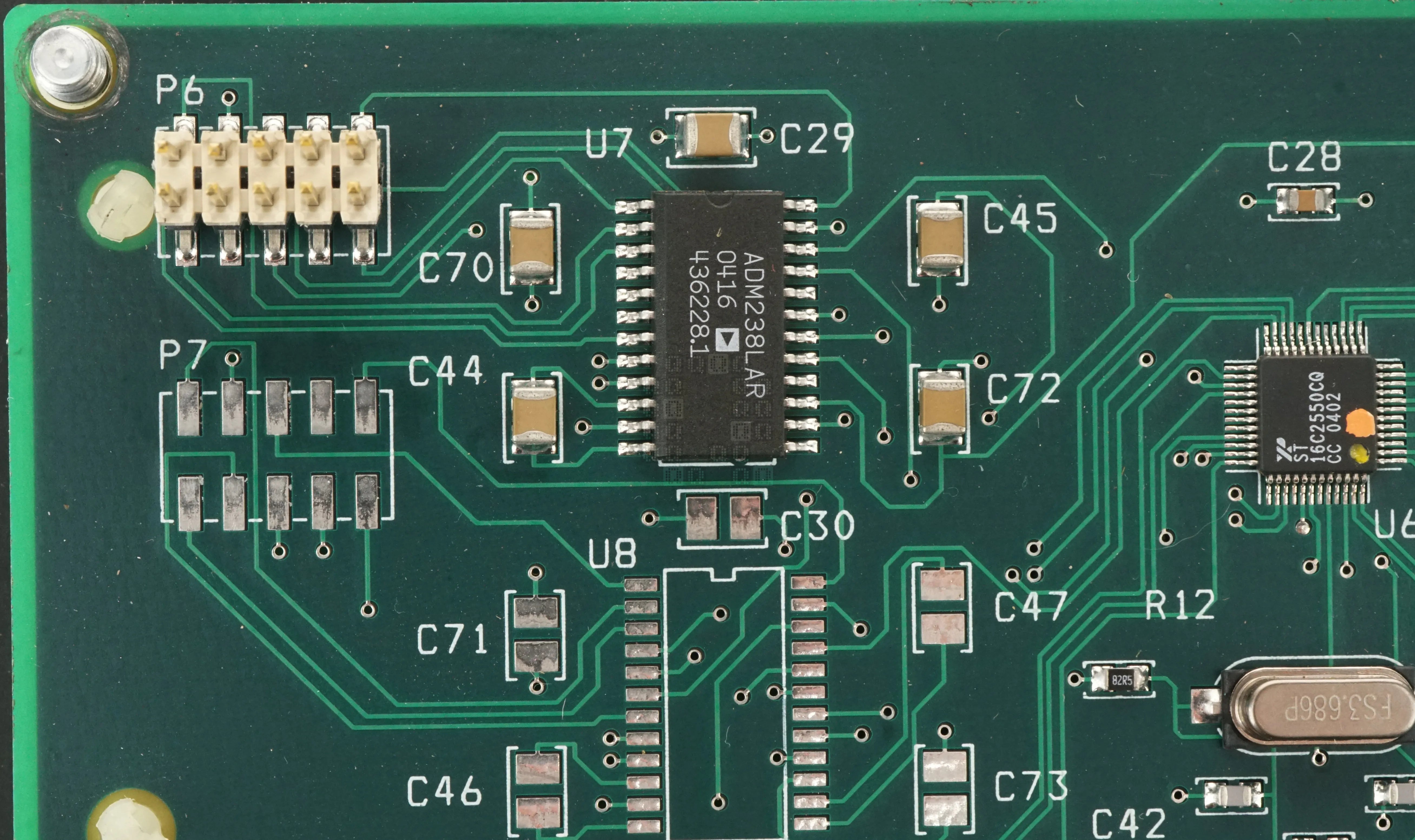
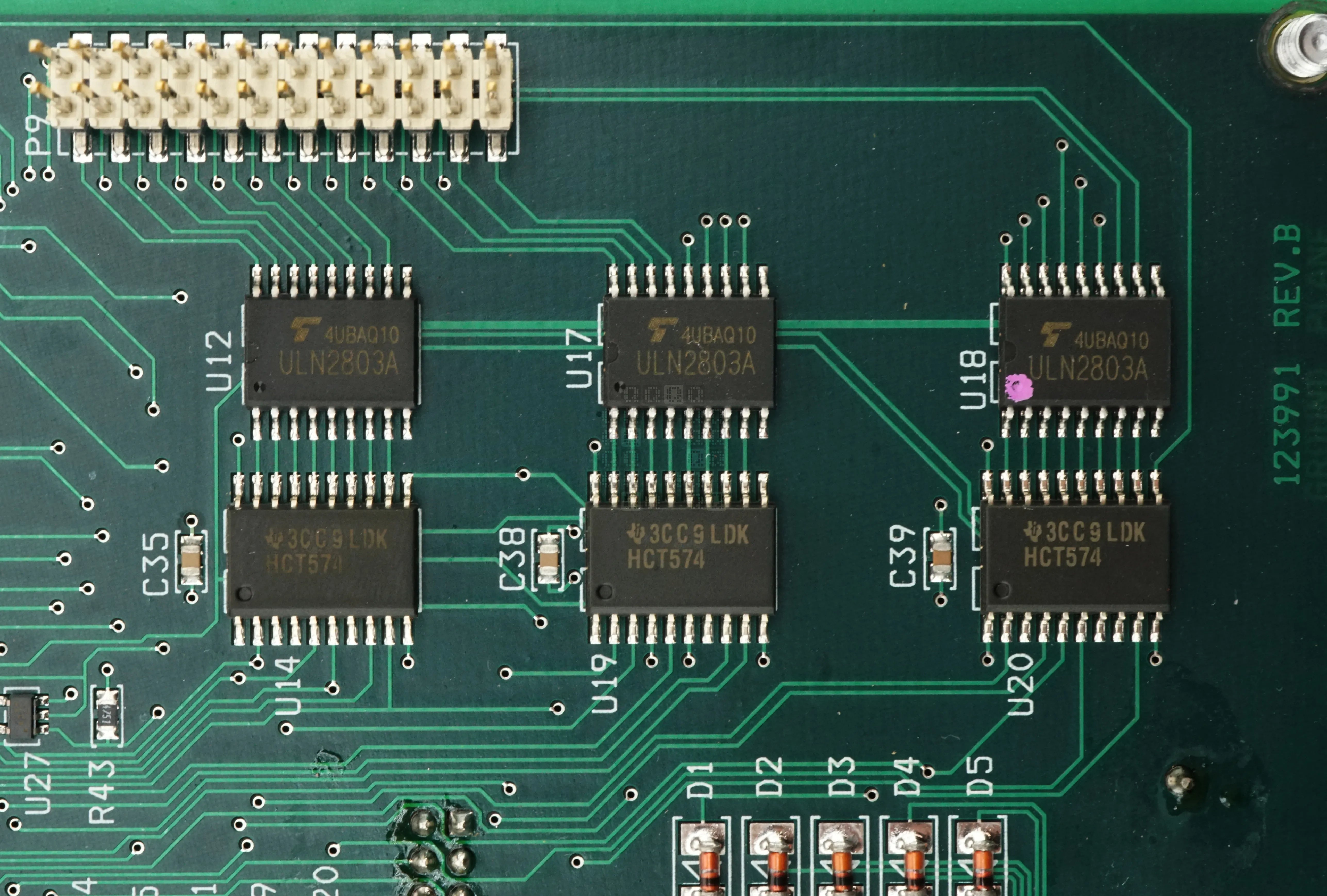
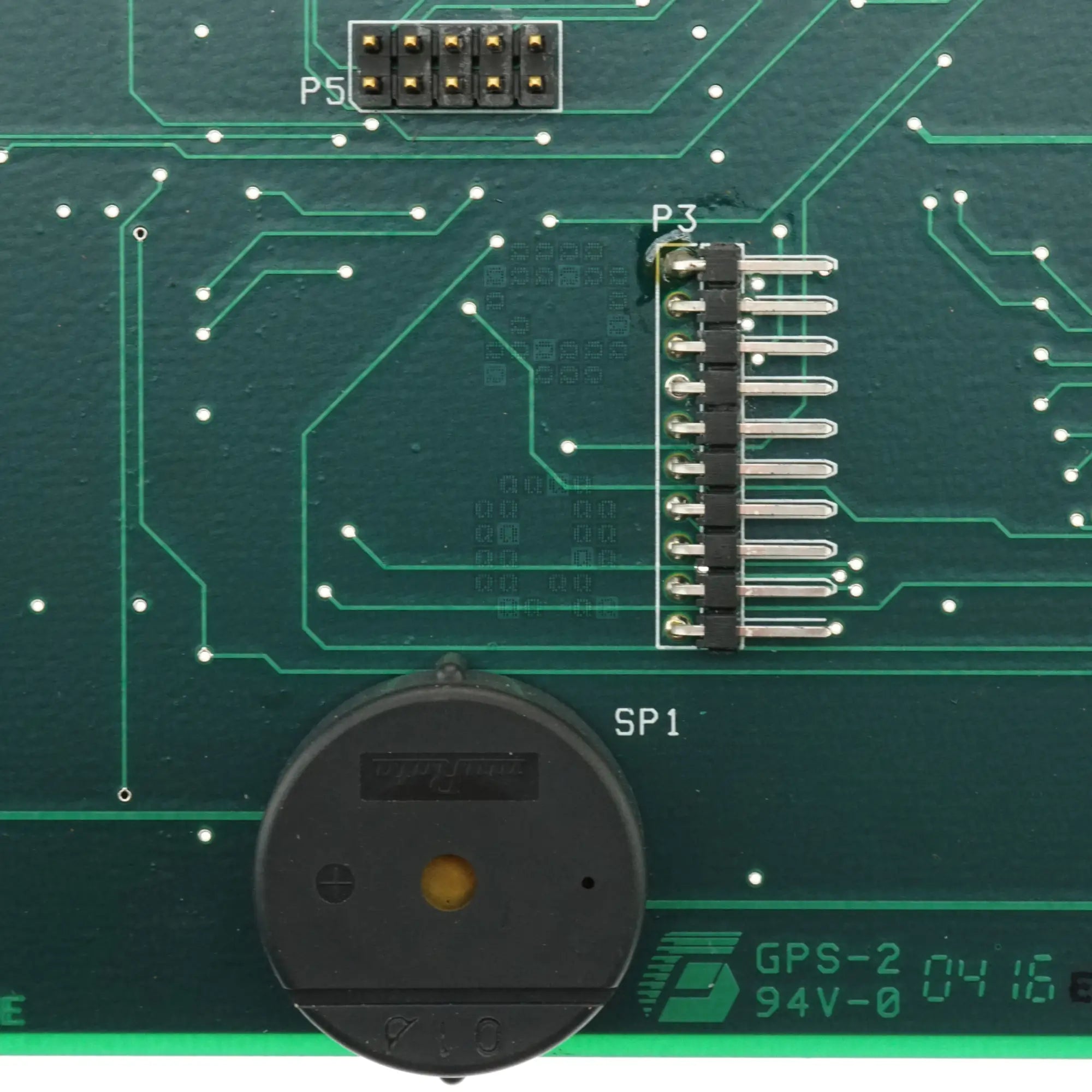
This is the 10-Pin Keypad interface. Also the really loud beeper.
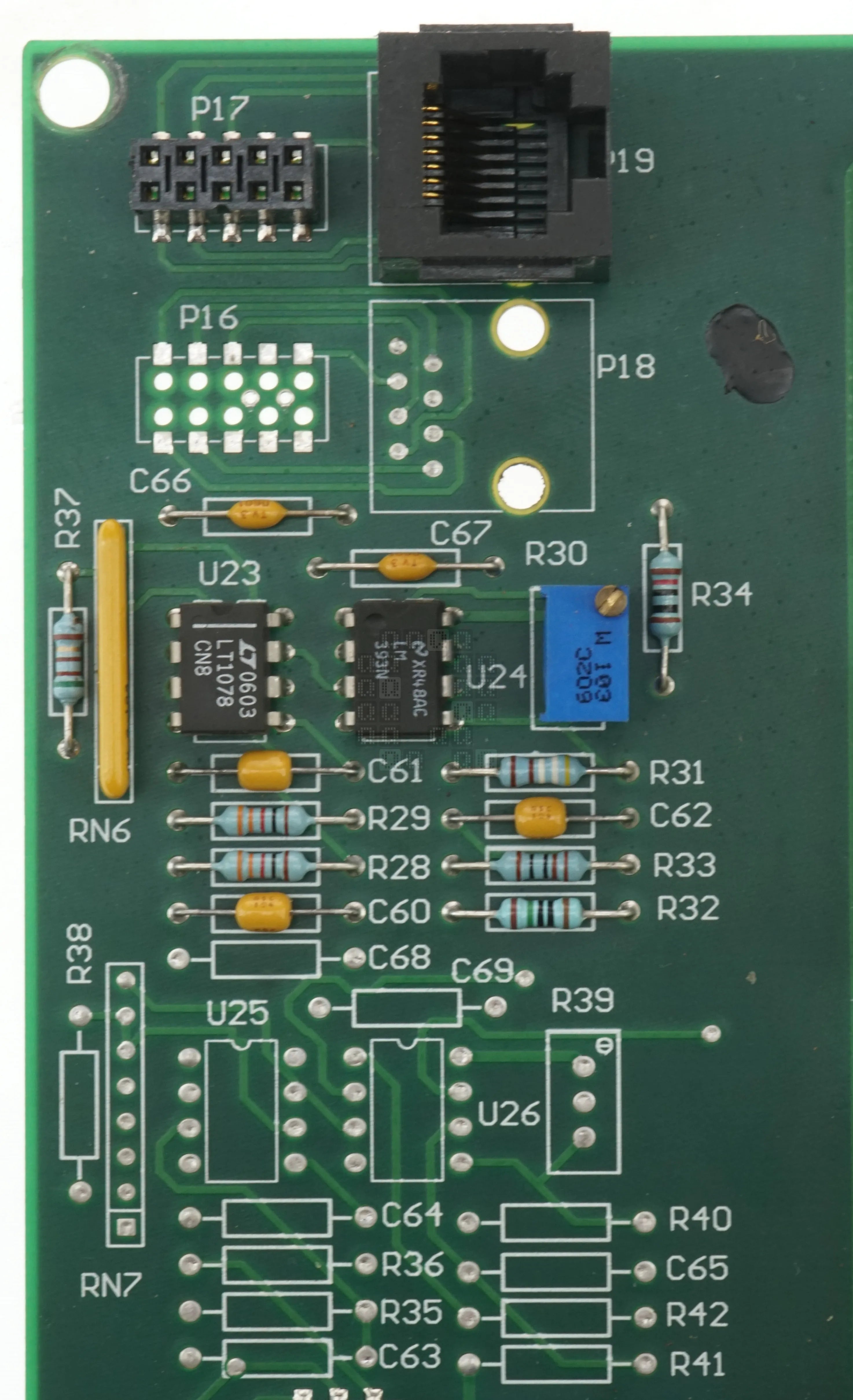
Here is a quick picture of the serial interface. P19 is wired directly to P17. U23 & U24 are op-amps.
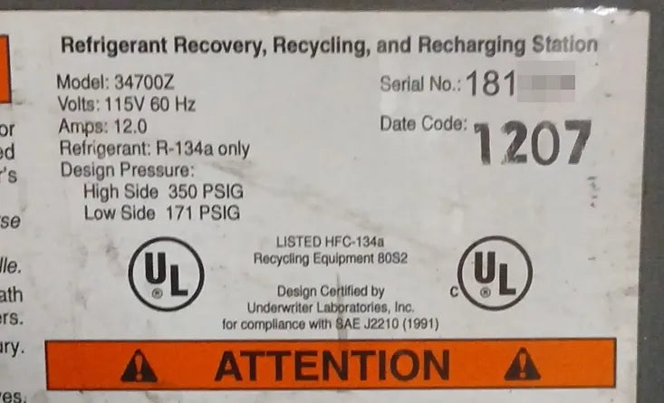
And this is the product label on the machine.
And this is the end of my fix of this board and the time consuming writeup. Hope its useful to someone!