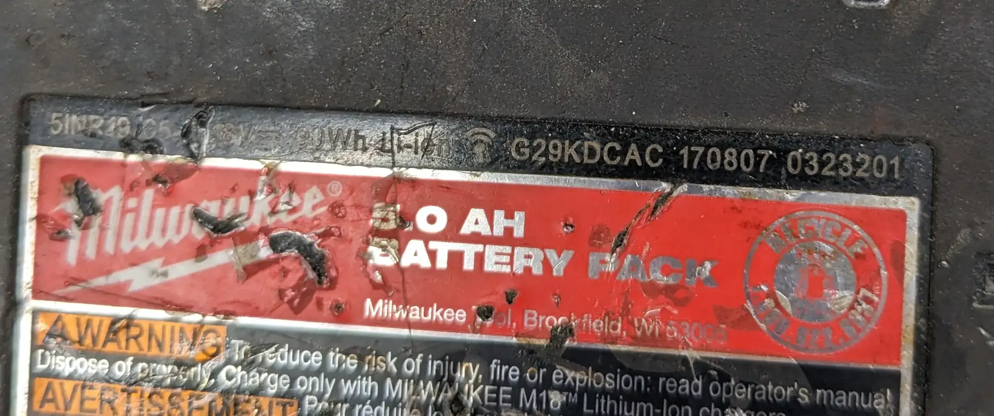
2023-03-08: I'm trying to work on a different version of the M18 Battery Controller board. This particular battery is a Milwaukee 5INR19-65 with serial number #G29KDCAC 170807 0323201. Here is the start of this project. The previous PCB reverse engineering project can be found here. I'm going to skip past disassembling the battery and jump right into the circuit board itself.
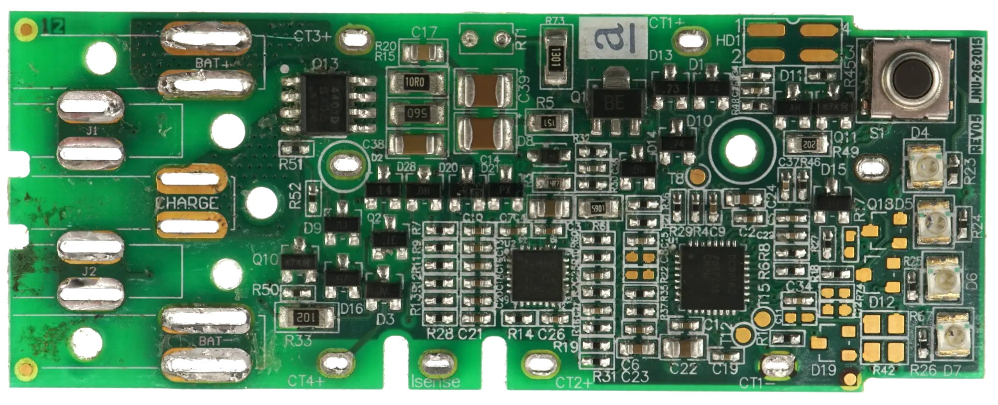
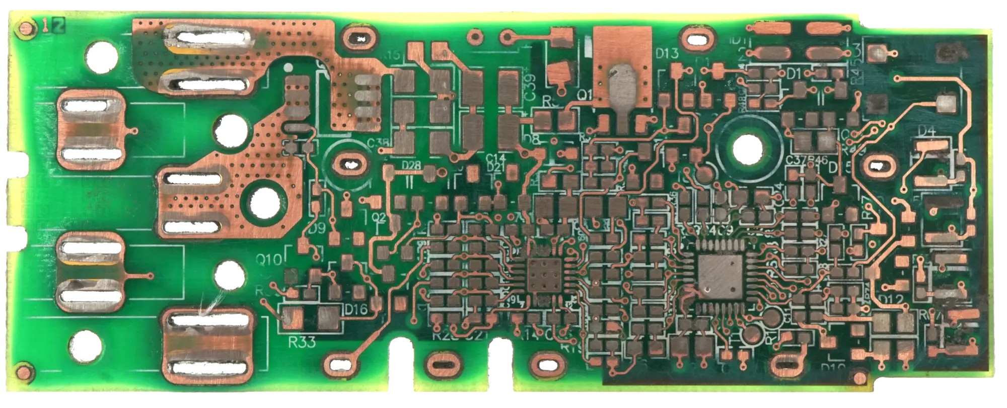
Top of Board
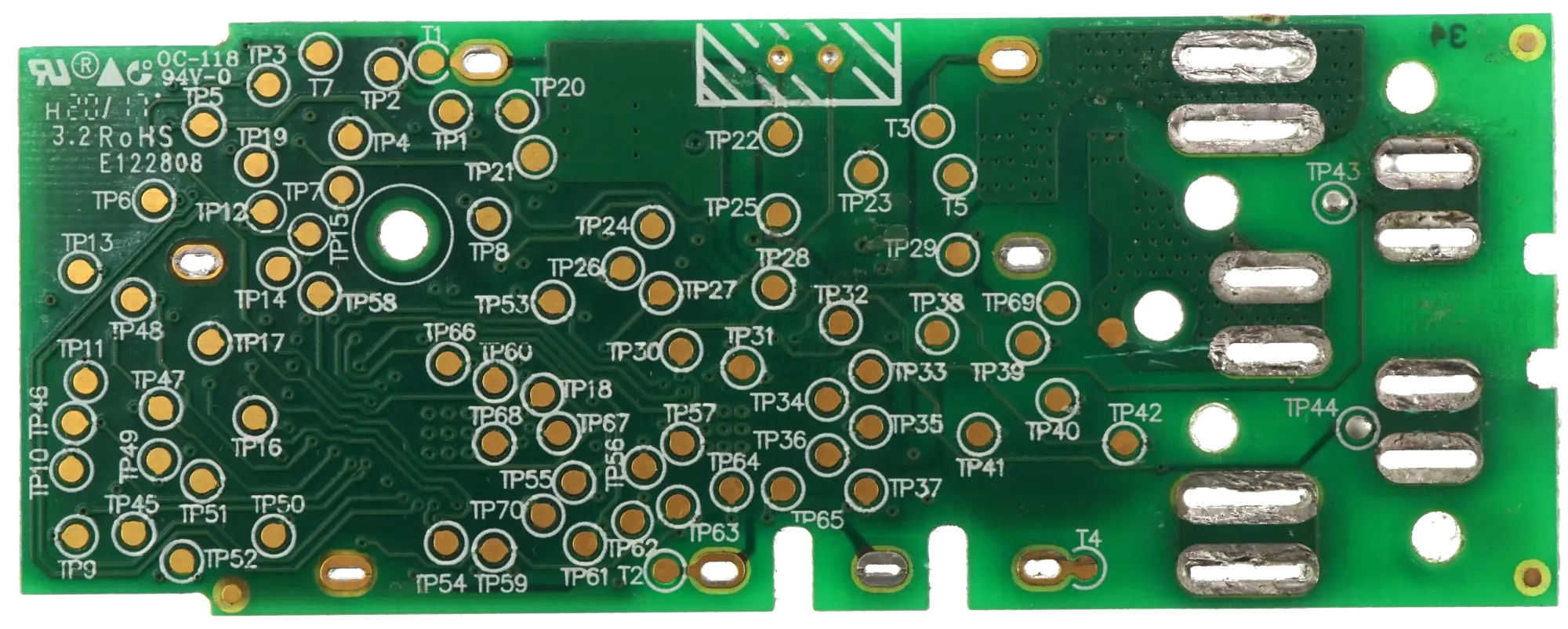
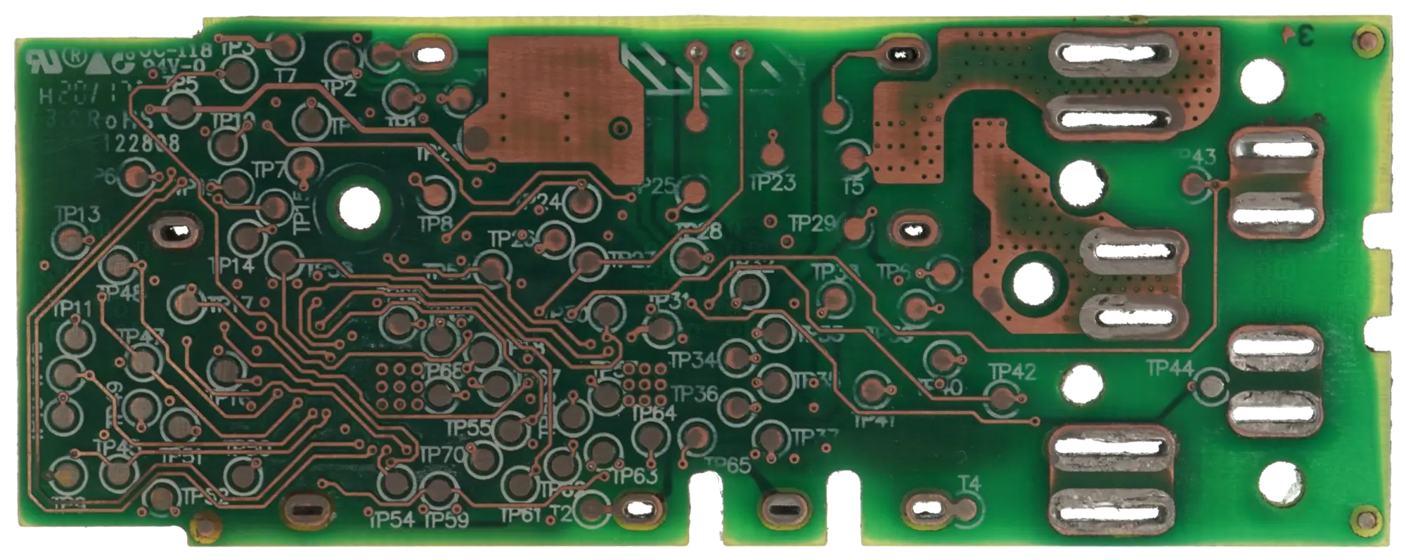
Bottom of Board
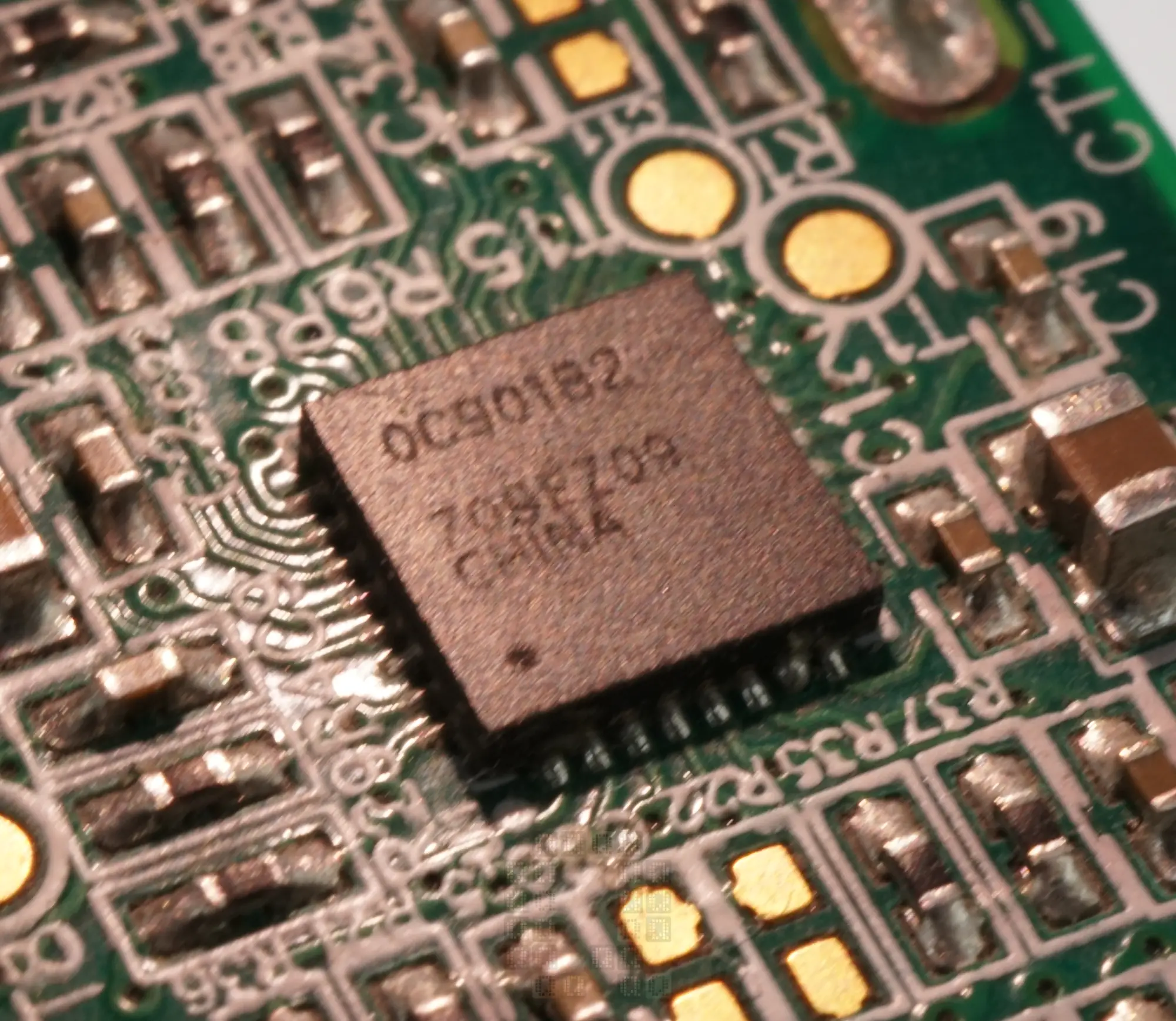
Milwaukee kept the Texas Instruments BQ76925 3 to 6 Series Cell Li-Ion Battery Monitor IC, but changed the microcontroller to a Renesas R7F0C901B2 (which is now discontinued). Some things were removed (second un-used RT2) and there are a lot of unpopulated parts on this board.
Desoldering the parts didn't go so well on this board. There are numerous pads that moved or got damaged. Nothing terrible, just annoying. This is the top Layer 1 copper.
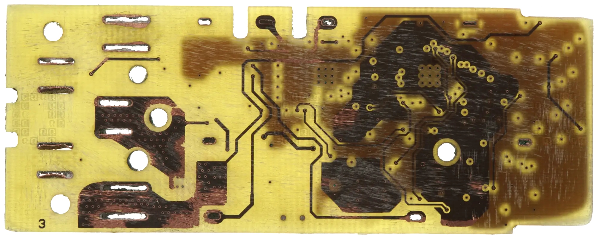
Layer 4 Copper (Bottom of circuit board)
Internal Layer 3 Copper. Didn't do so well on this layer either... I managed to go a little deep a couple different places. Everything is at least obvious as to where it is supposed go.
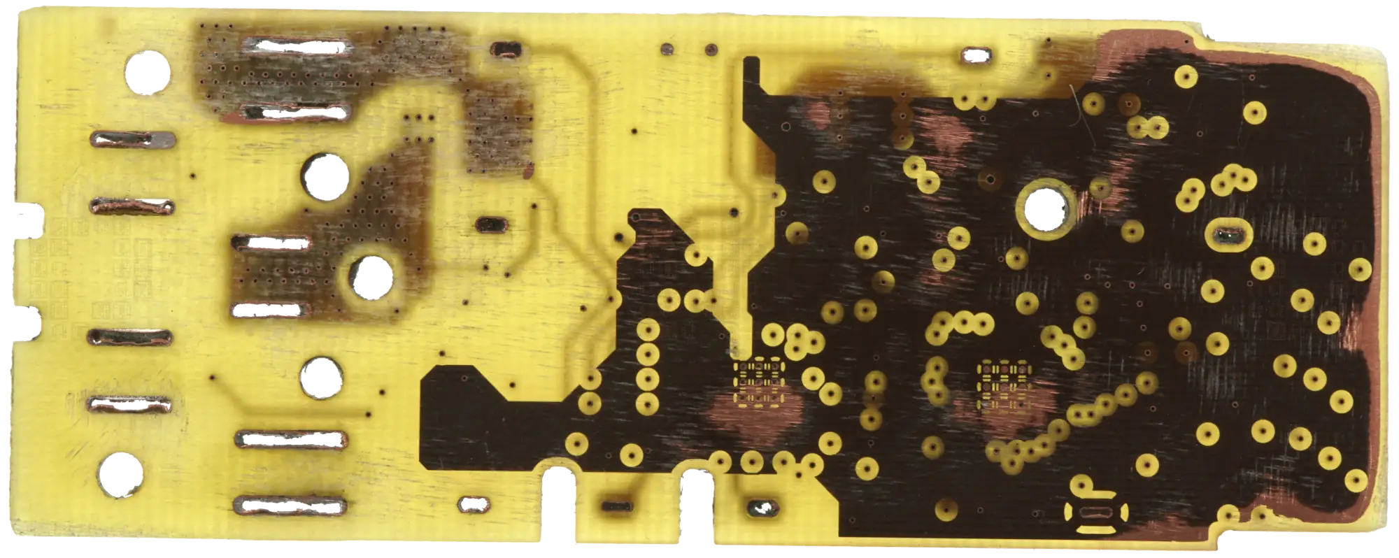
Layer 2 Copper
Here is a link to a partial BOM (PDF, 25KB) for the circuit board (there are mistakes and omissions). And here is link to a image file (ZIP-XCF-GIMP, 61MB) showing all the circuit board copper layers in a nicer, easier to work with form. The electrical diagrams for the BQ76925 are quite similar to the previous project, while areas around the R7F0C901B2 have been updated. I'm going to stop posting info on this board for right now... Always other things to work on - there may be updates in the future. This should give a good start to anyone looking to discover more info about this circuit board.
And as always, clicking on an image will give you a higher-res version! If you repost or further dissect this board with info from this page, please link back to the original and let us know where we can read about your work!

