
Please Note: Clicking on an image will take you to a higher resolution version of the image you clicked on.
2026-08-01: This is a quick exploration of the 2800-20 M18 Communication Adapter. It is a newer version of the Milwaukee 2700-20 ONE-KEY Adapter I've previously explored.
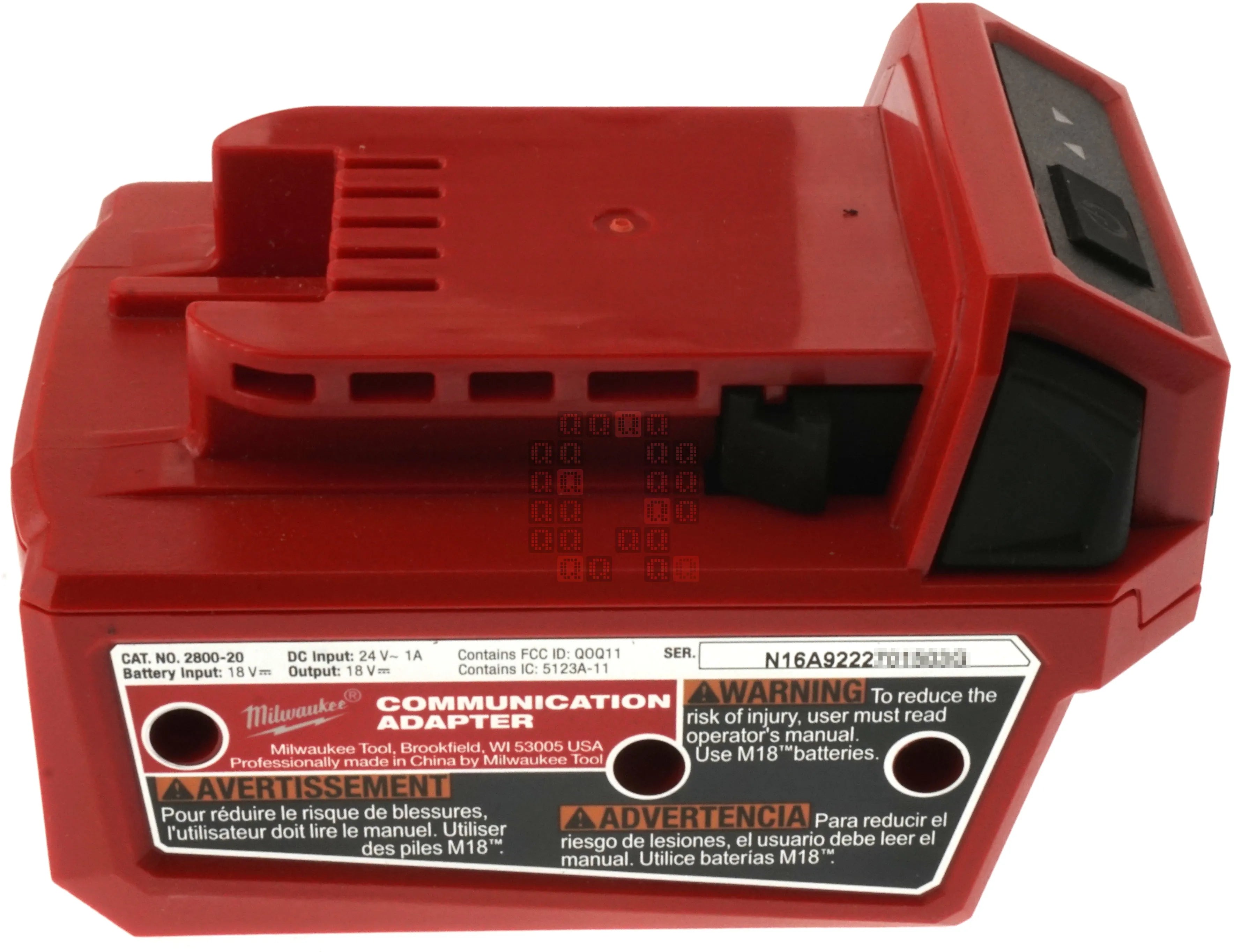
Label for the tool we're going to explore: the Milwaukee Tool M18 Communication Adapter, Catalog Number 2800-20, FCC ID Q0Q11 (we'll look for that later) and a note that says 'Contains IC: 5123A-11'. Here is a link to the instruction sheet for the tool. There is no Operator's Manual. Three screw holes visible on this side.
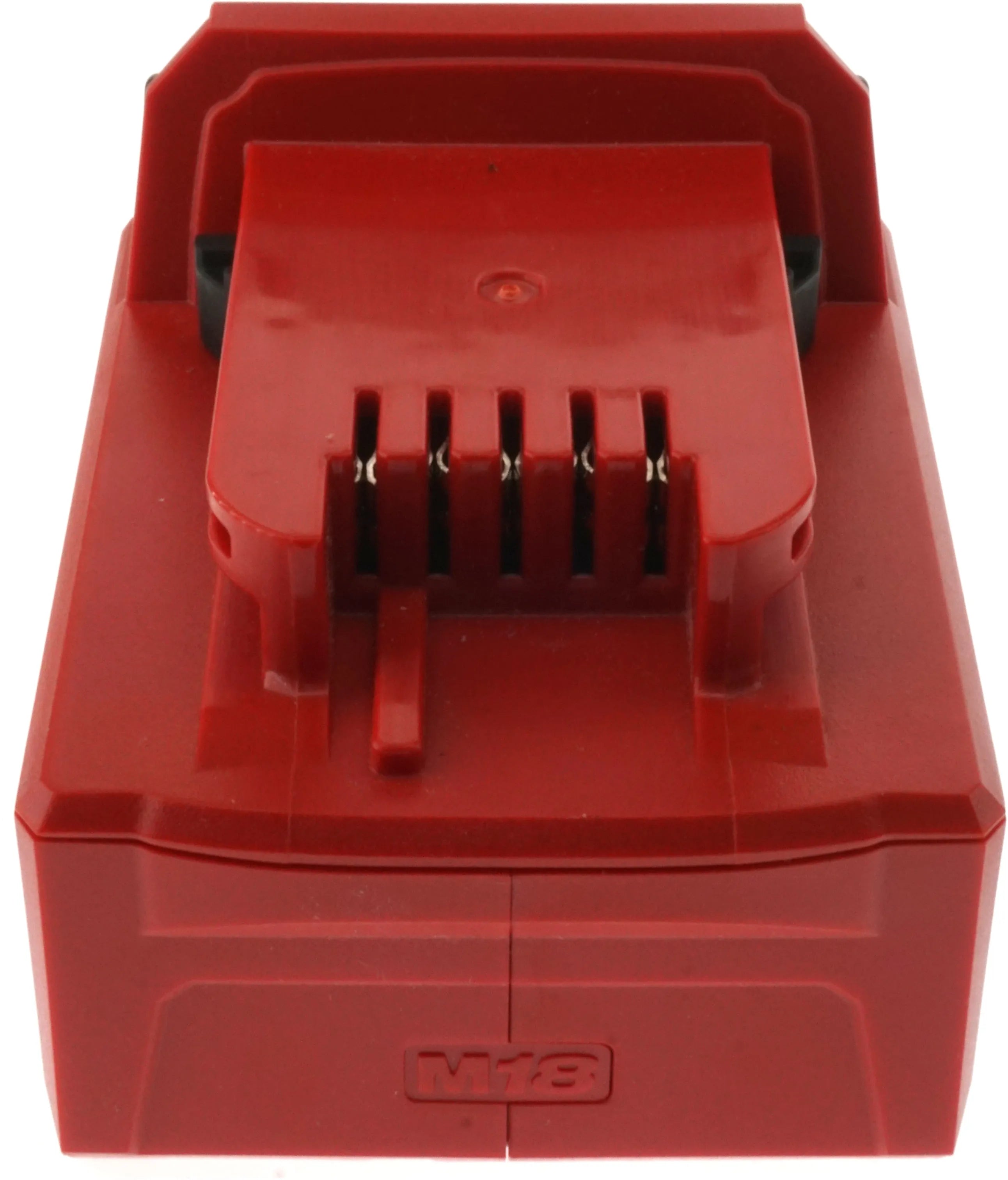
This is the tool end of the adapter. Looks pretty standard if you've seen M18 batteries.
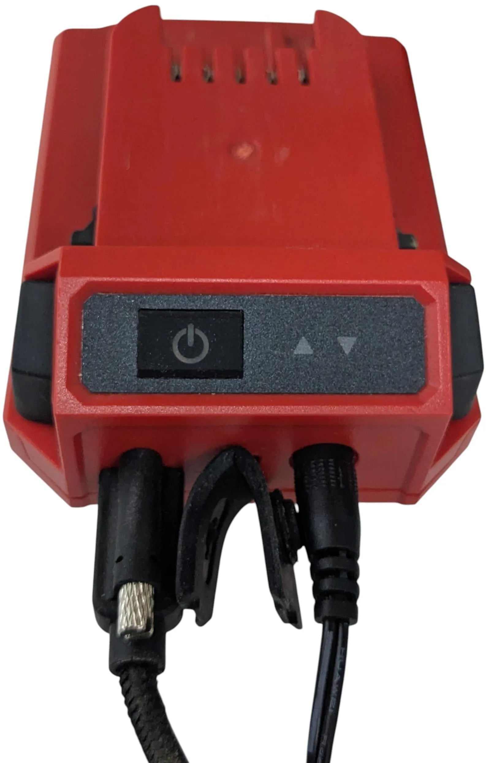
This is the user interface... One illuminated push button and two LED's. There are exactly two connections, a locking(!) USB-C connection and a 24VDC 1 Amp power adapter input which is not locking. Power for the unit is supplied by the power adapter, not the USB port. Device shows up on a windows computer as two USB Serial devices.
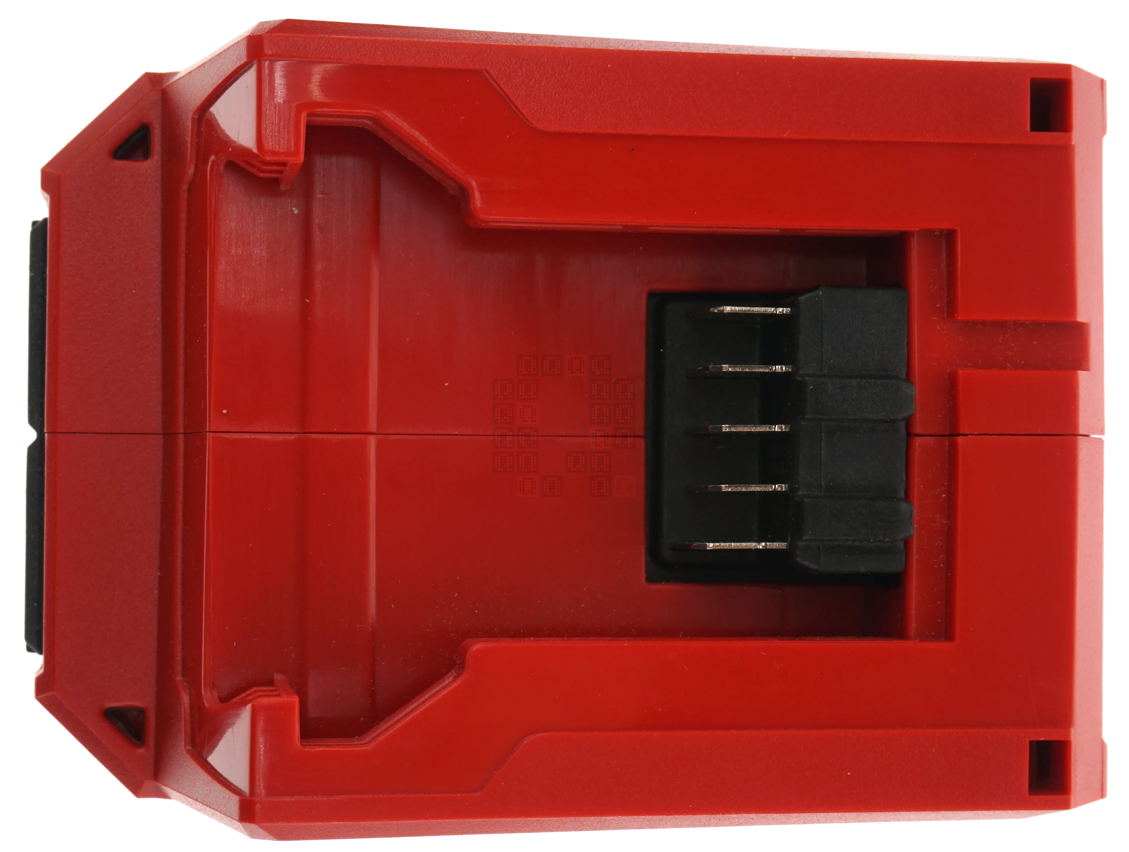
Battery side of the tool. Again pretty standard here if you've looked at the bottom of any M18 tool.
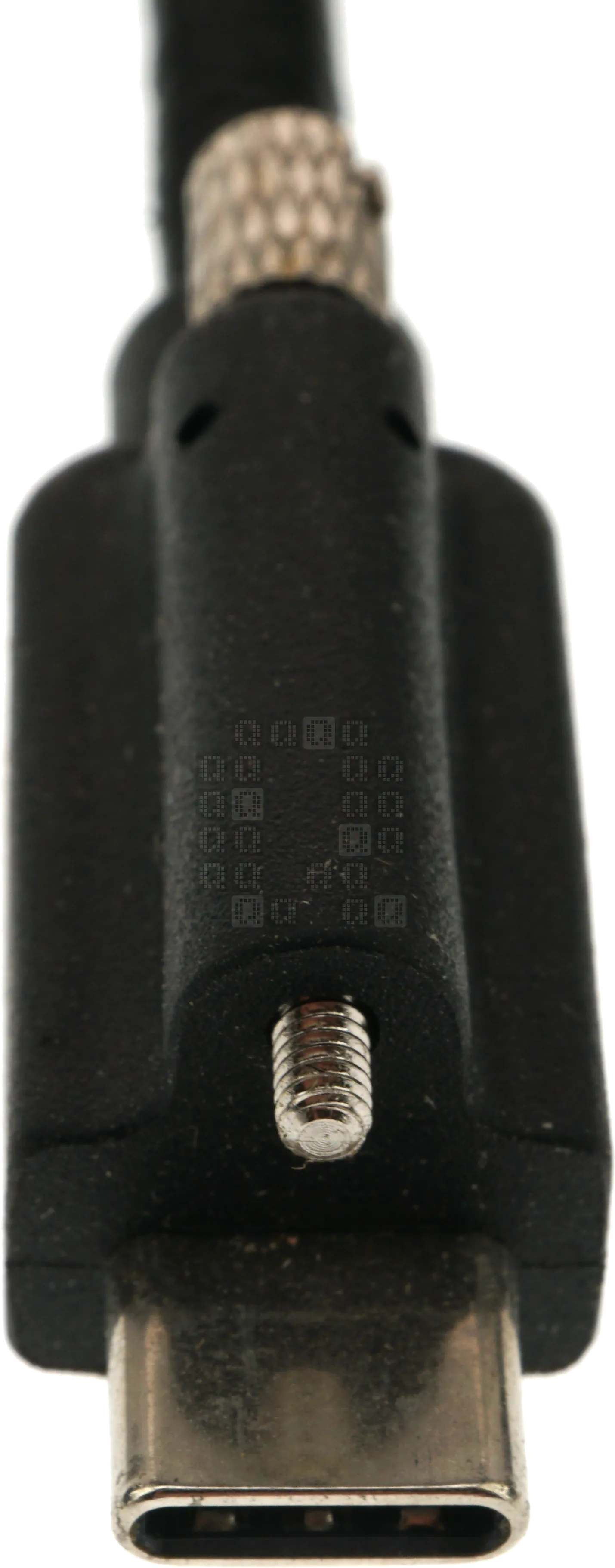
I had to stop and take a picture of this: a locking USB-C connector. Haven't seen one of these before. No manufacturer markings on it that I can find.
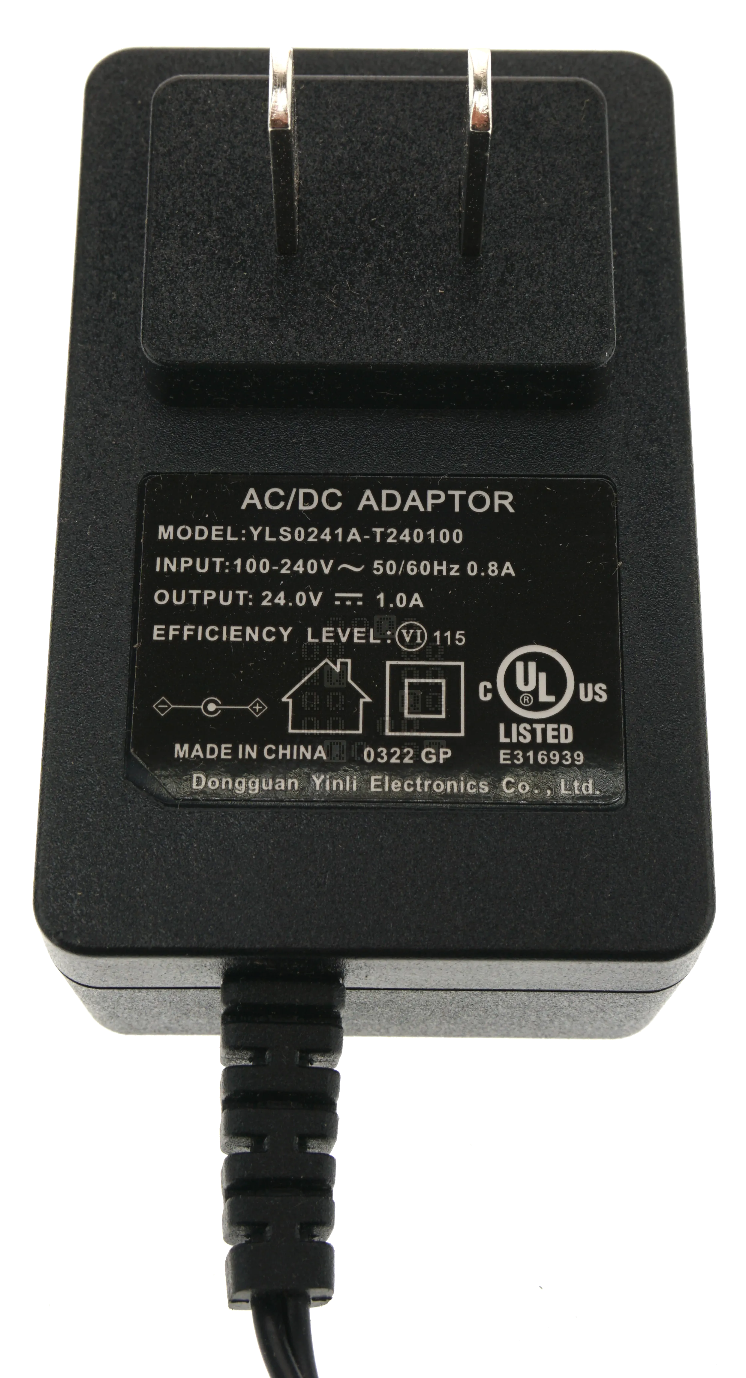
And we should probably look the power adapter too - Dongguan Yinli Electronics Co., Ltd. YLS0241A-T240100 100-240VAC 50/60Hz 0.8A; Output: 24.0VDC 1.0A 24-Watts. (Hmm even at 100V@0.8A thats 80-watts in and 24-Watts out - that's 30% efficiency... and the unit is marked Efficiency: VI - that is >=88% ) They're for sale, but I couldn't find a datasheet.
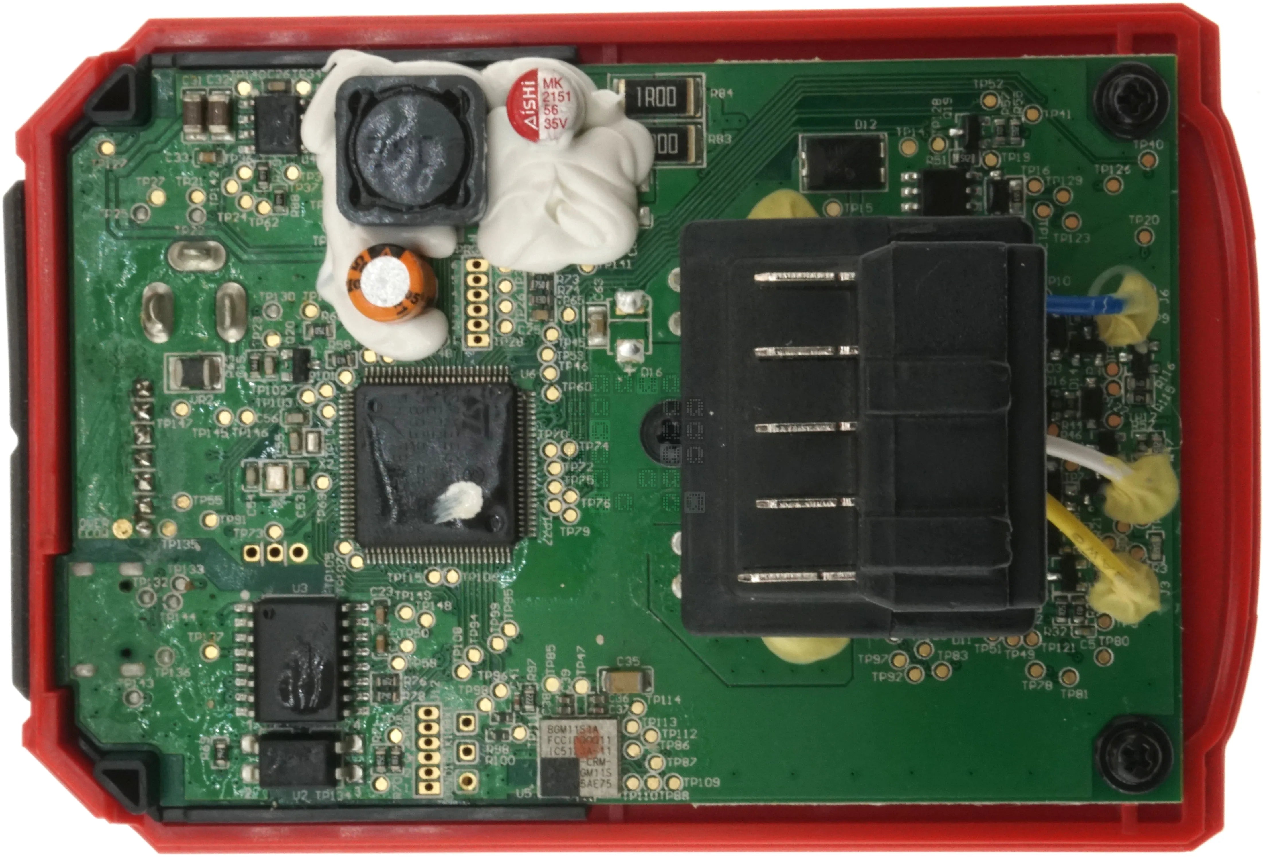
You can start to disassemble this by removing the 3 screws on the side. (see above label image) The two halves split away from the center to show you the battery side of the circuit board. Two more screws remove this circuit board from the top cover (tool side) of the adapter. One interesting thing here is the slightly longer connection for the negative terminal [bottom] - I've not noticed this before on other Milwaukee tools, but I'm going to need to look for it now. I'll look at the ICs in a little bit.
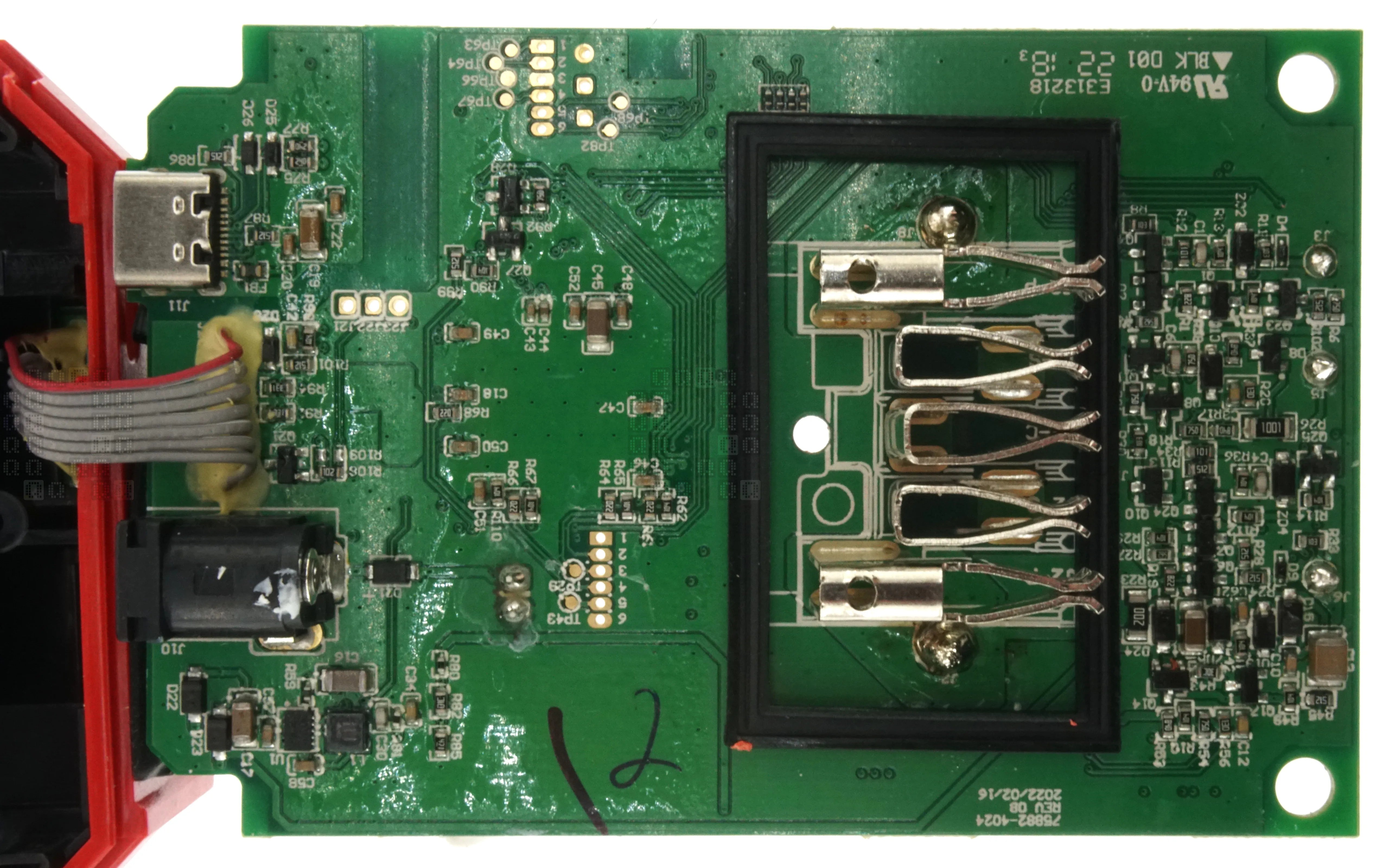
This is the tool side of the circuit adapater. There is a label - 75882-4024 Rev 0B 2022/02/16. Most of the 'low tech' parts are on this side, but there are definitely a lot of them!
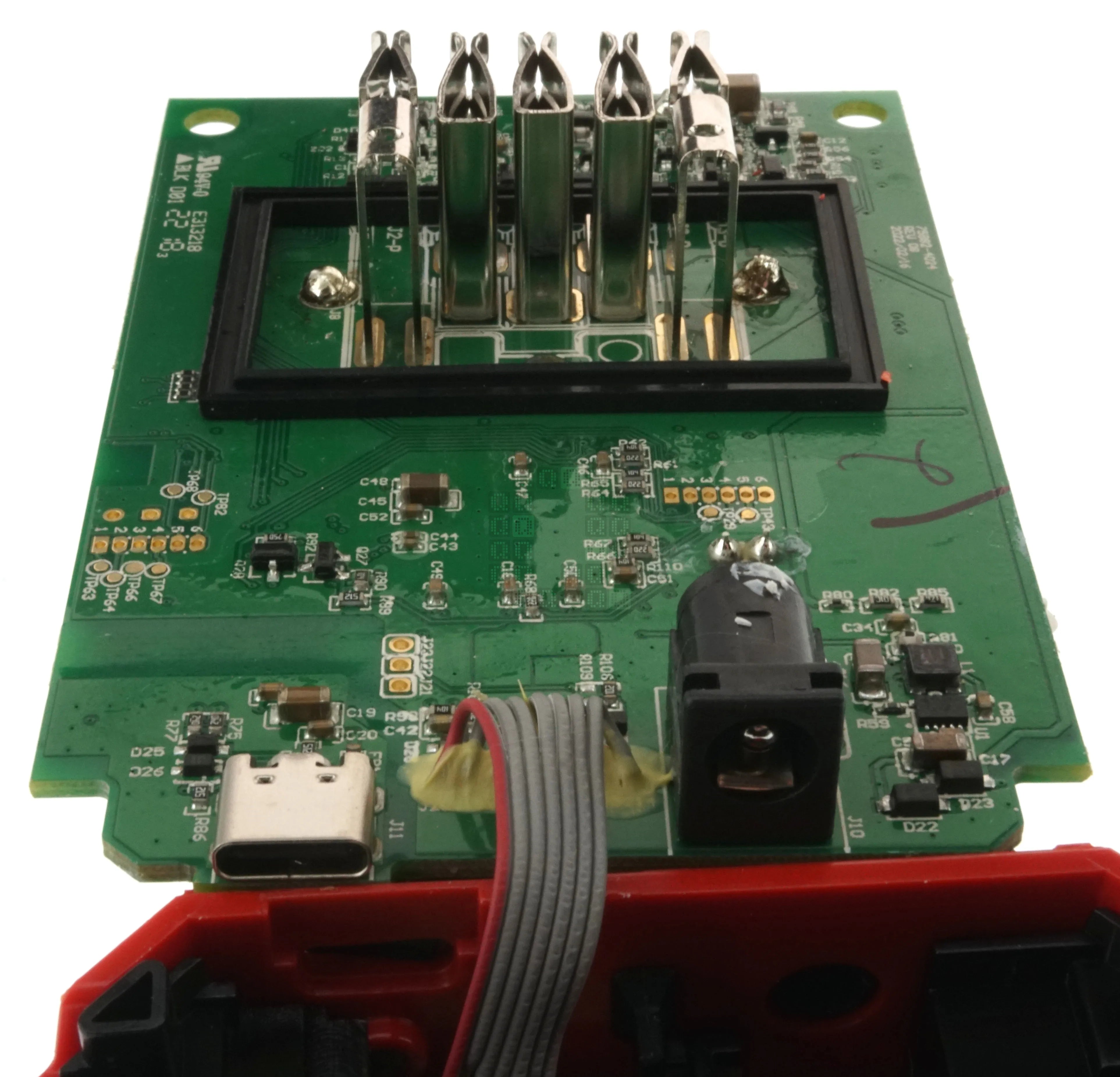
A quick image from the user interface side to show the ports. There is a little brass threaded insert in the housing above the USB-C port to provide the locking functionality. The circuitry to the right of the power jack appears to be a buck regulation IC on the other side of the board.
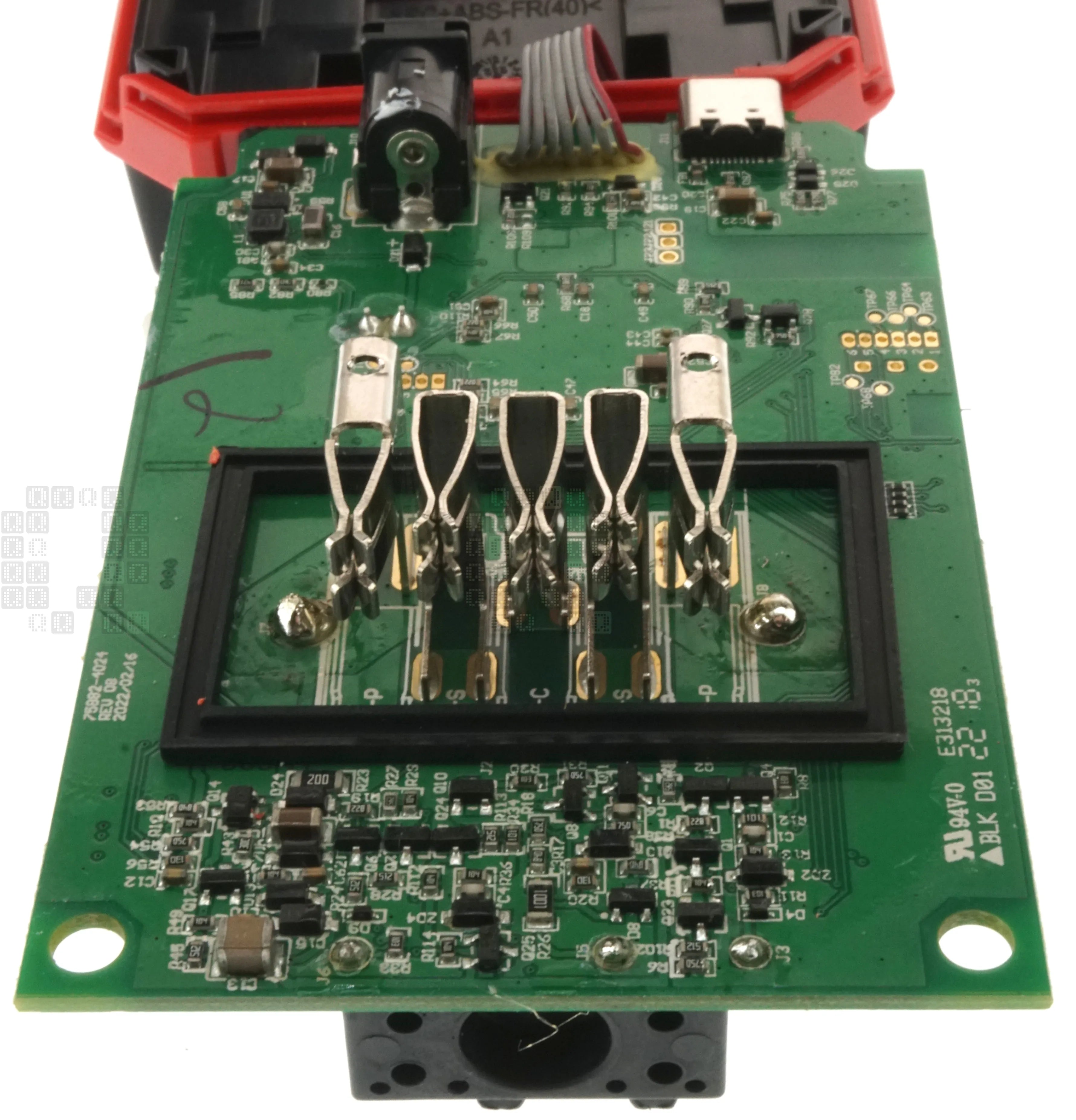
One more image from the tool connector side of the circuit board.
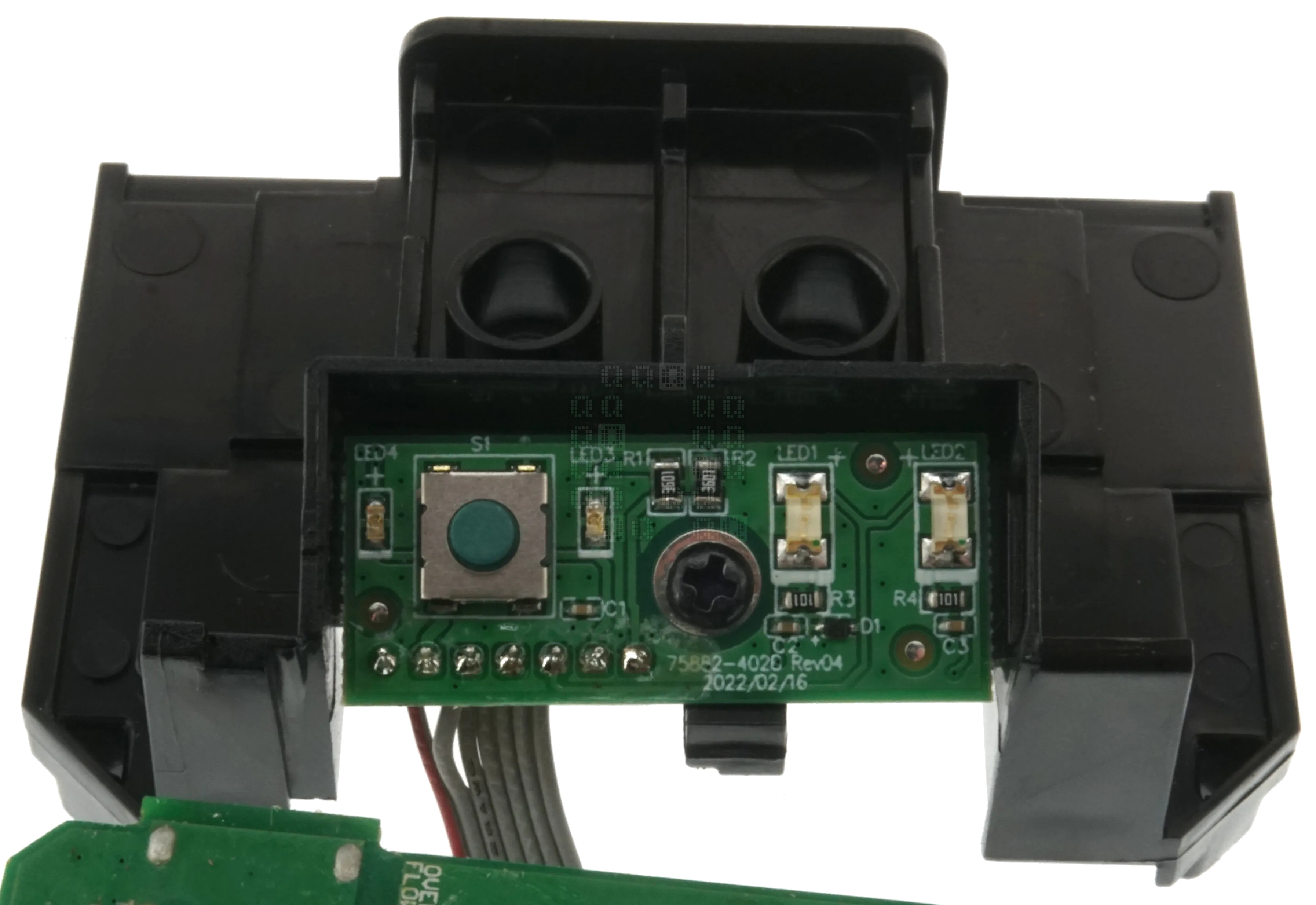
This is the entirety of the user interface. Did I say two LEDs earlier? There are 4 total - but two are used for lighting up the pushbutton. This circuit board is labeled as 75882-4020 Rev 04 2022/02/16. There are 7 wires going to this circuit board. That seems like at least one extra wire... (I may dive into this later)
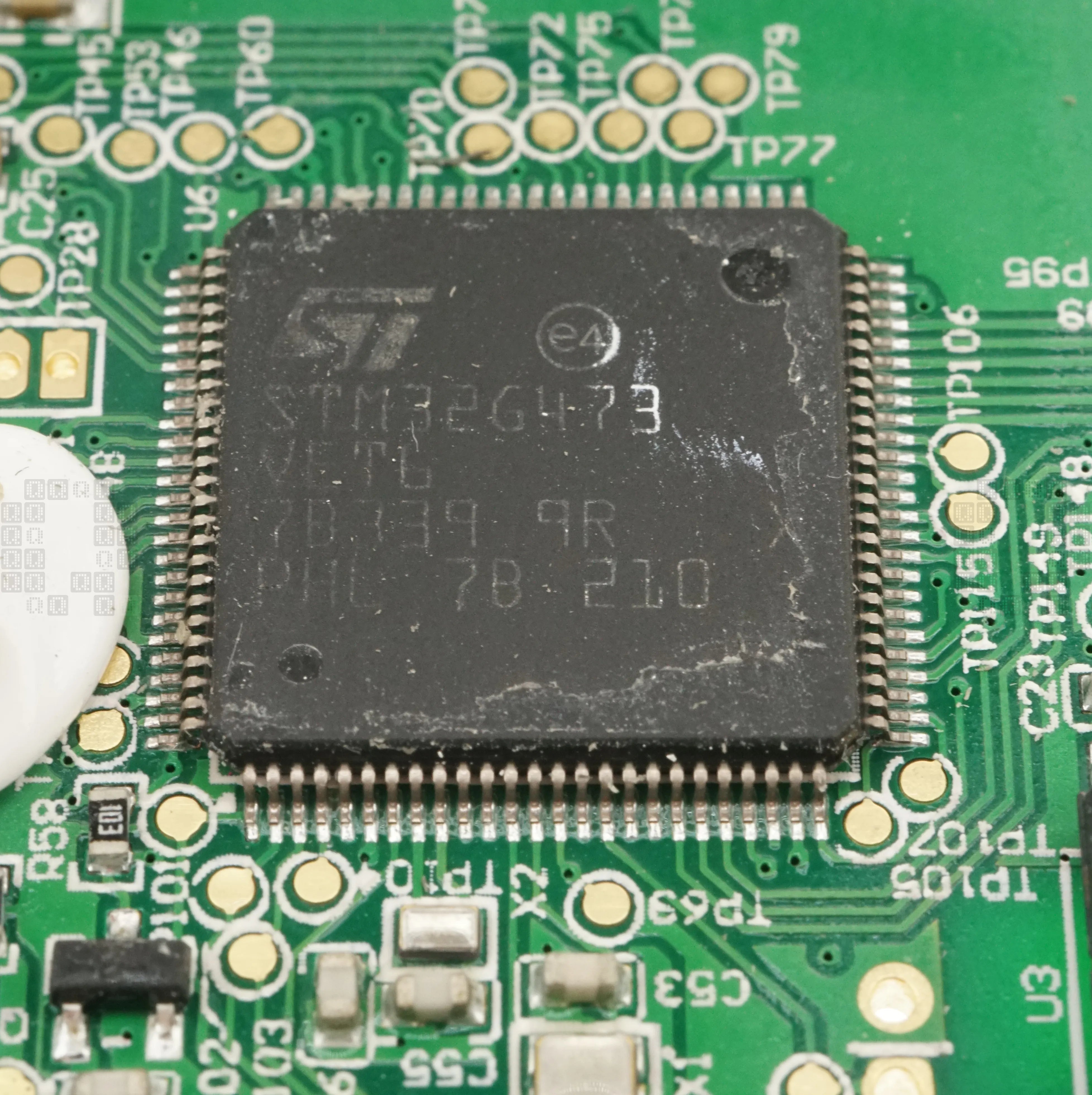
And now, the star of the circuit board: STM32G473VET6: an ARM Cortex-M4 32-bit MCU+FPU. 512KB Flash. 170MHz, 128KB SRAM, internal USB 2.0 Controller. Here is a link to the datasheet. There are 100 pins on this IC! (seems like a lot when you think about it a little...then you realize it might be pretty easy to use most of them...)
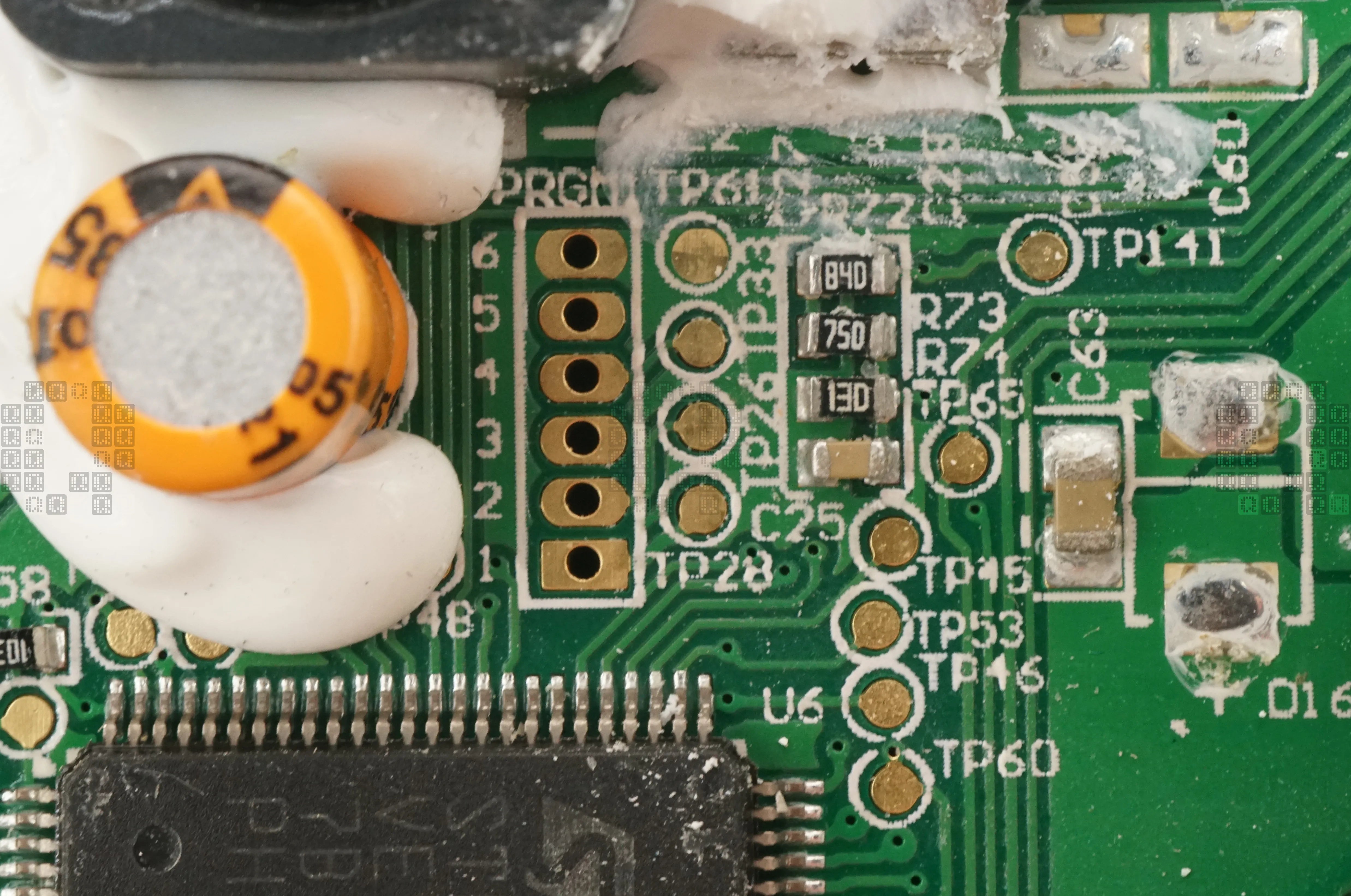
and since I've mentioned 'pins' I need to at least include an image of the 6-pin programming header for this CPU.
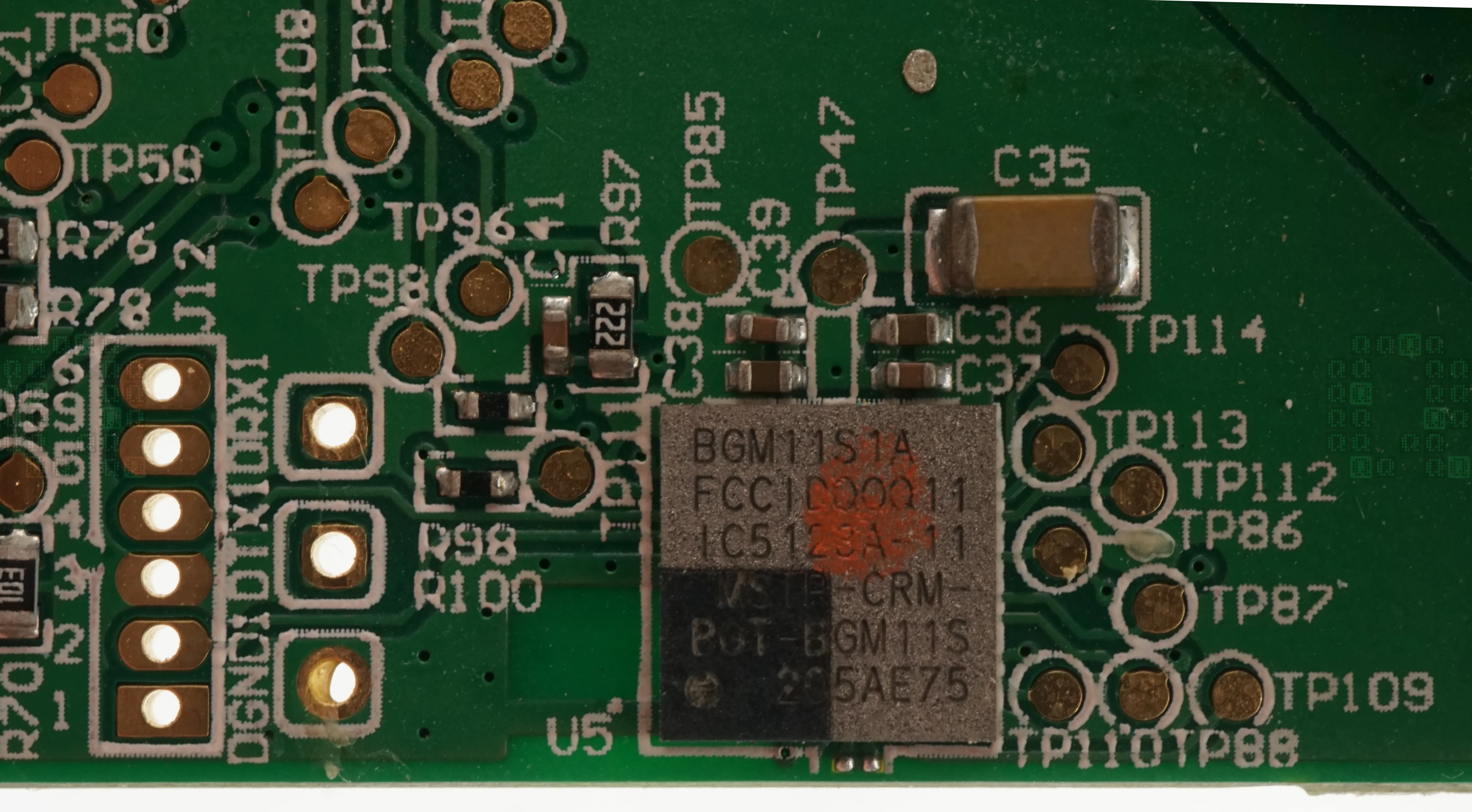
Silicon Labs BGM11S1A Blue Gecko Bluetooth SiP Module, FCC ID QOQ11. Another ARM Cortex M4 core running at 38.4 MHz with 256kB Flash & 32kB RAM. BLE 2.4 GHz. Here's a datasheet for this part. Here is a link to the FCC documents for the QOQ11 device (Silicon labs only - not the Milwaukee device) The 'Contains IC: 5123A-11' note on the label is explained in the datasheet - there has to be a label on the outside of the device where it is visible to the end user. This note is just another reference to this IC.
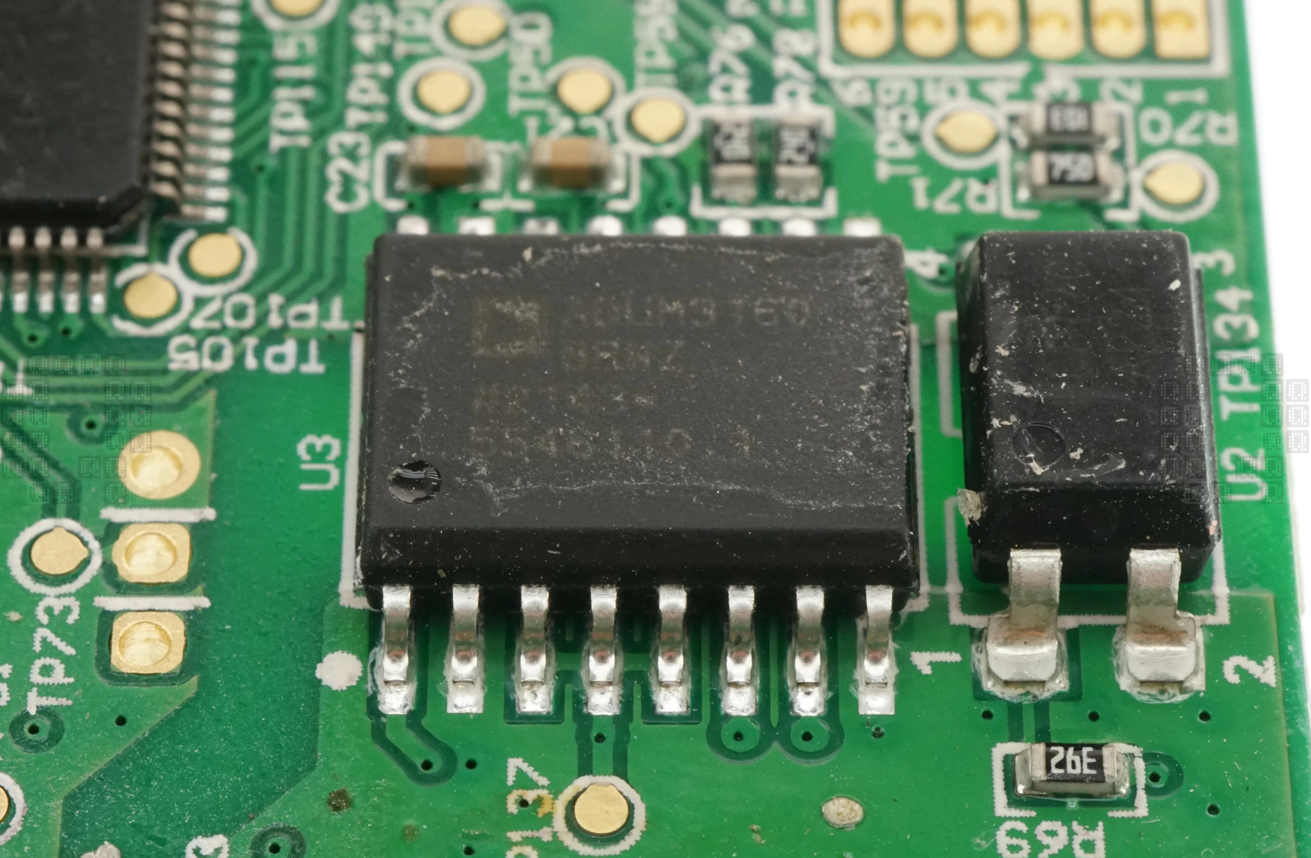
Analog Devices ADuM3160BRWZ Full/Low Speed USB Digital Isolator. Datasheet here There is a PC817C opto-isolator to the right of this IC.
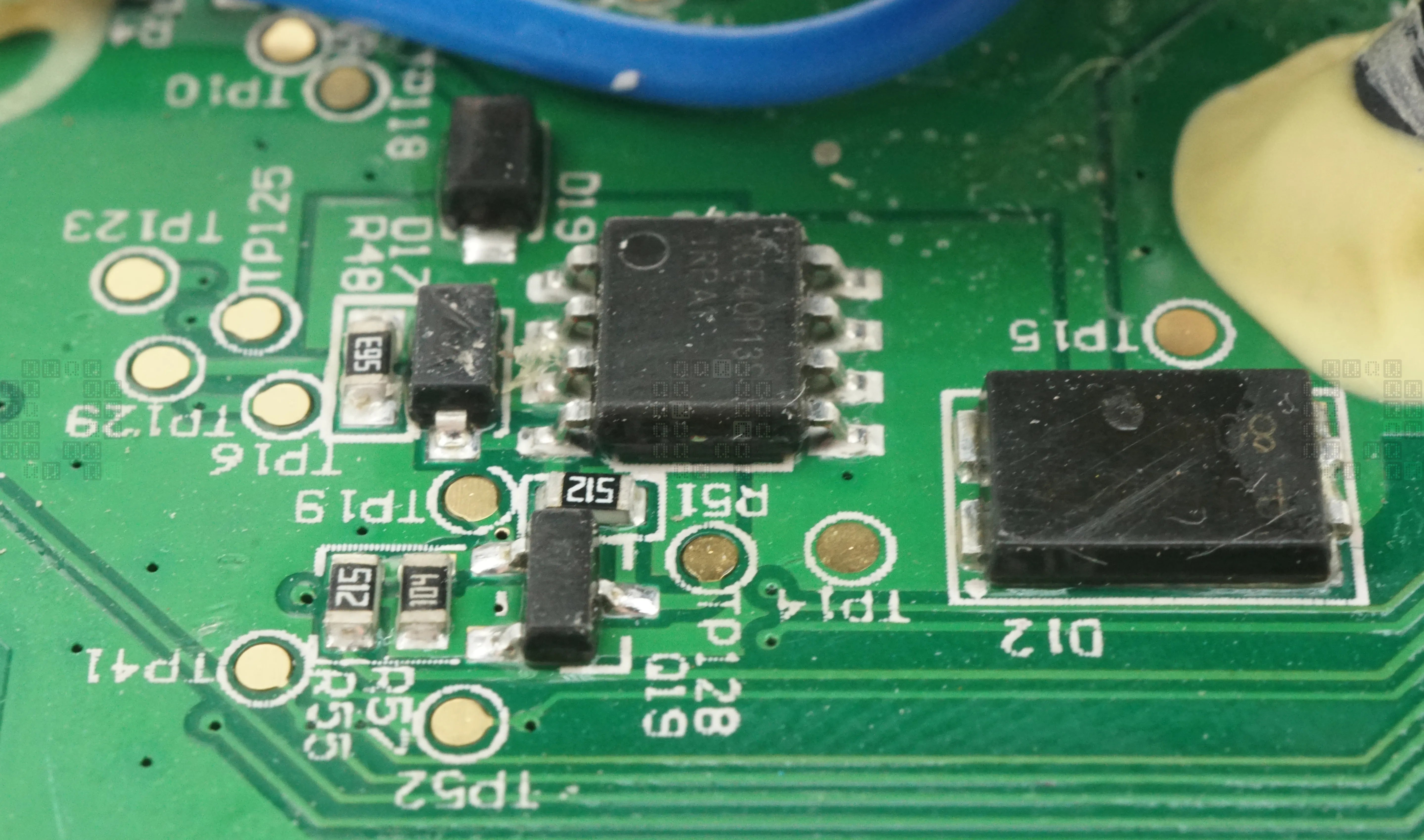
The SOIC-8 is a NCE40P13S P-Channel MOSFET. D12 is labeled as PJ1D7GV 804B. It appears to control power to the tool side - allowing for reboots/resets of the tool microcontroller.
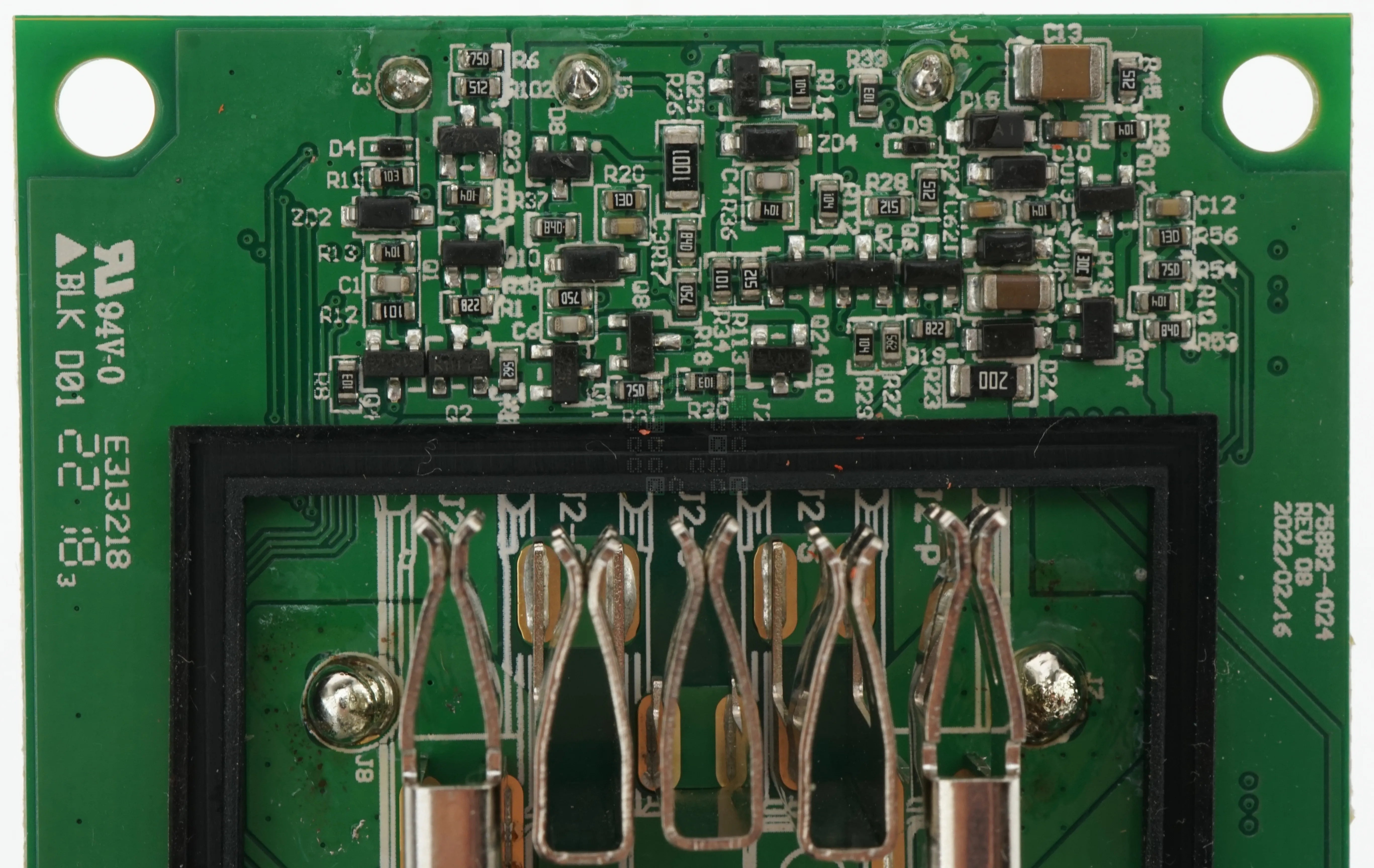
Transistors galore! These appear to be entirely for the 4 signal wires (2 each for the battery and tool).
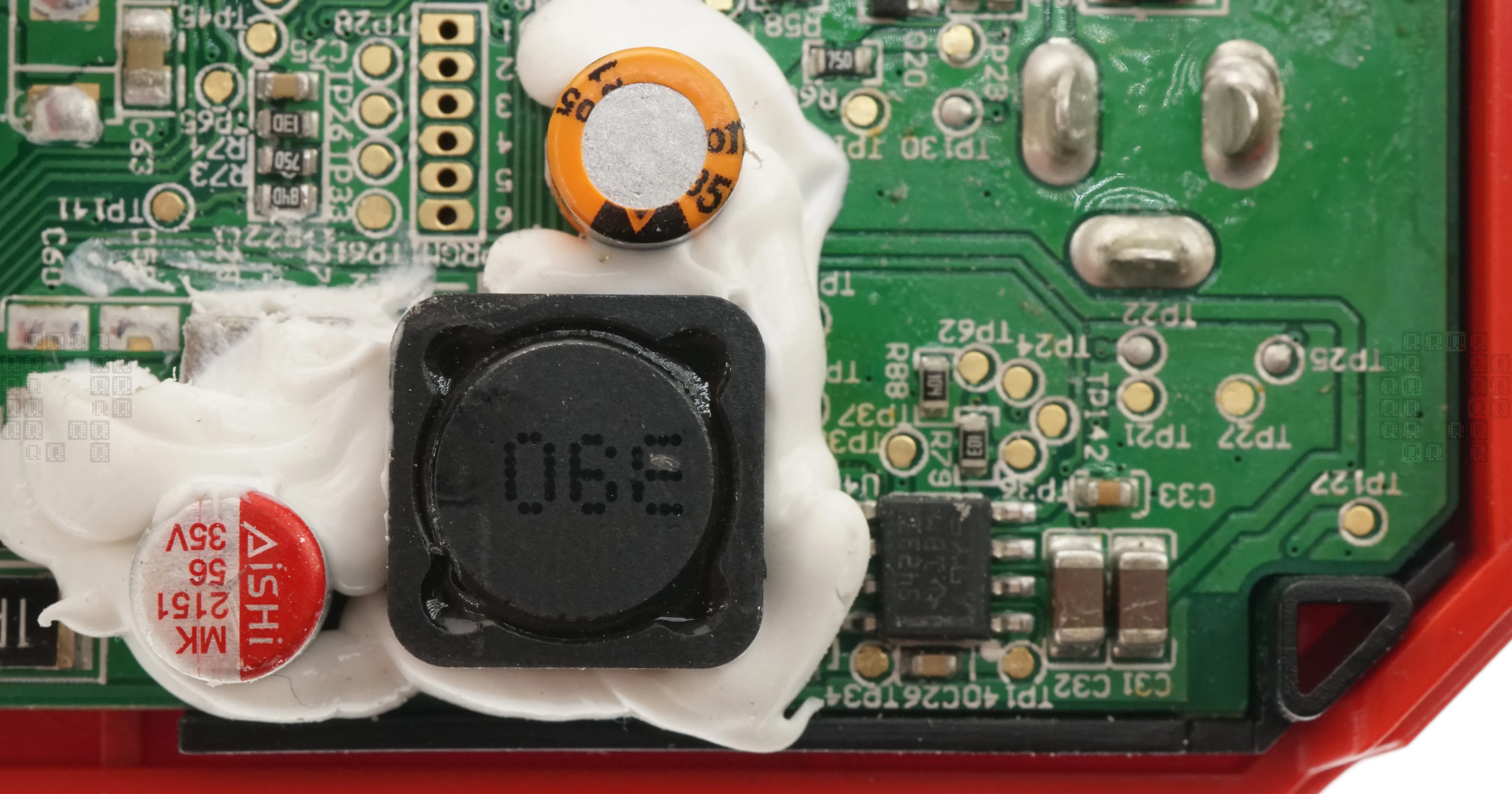
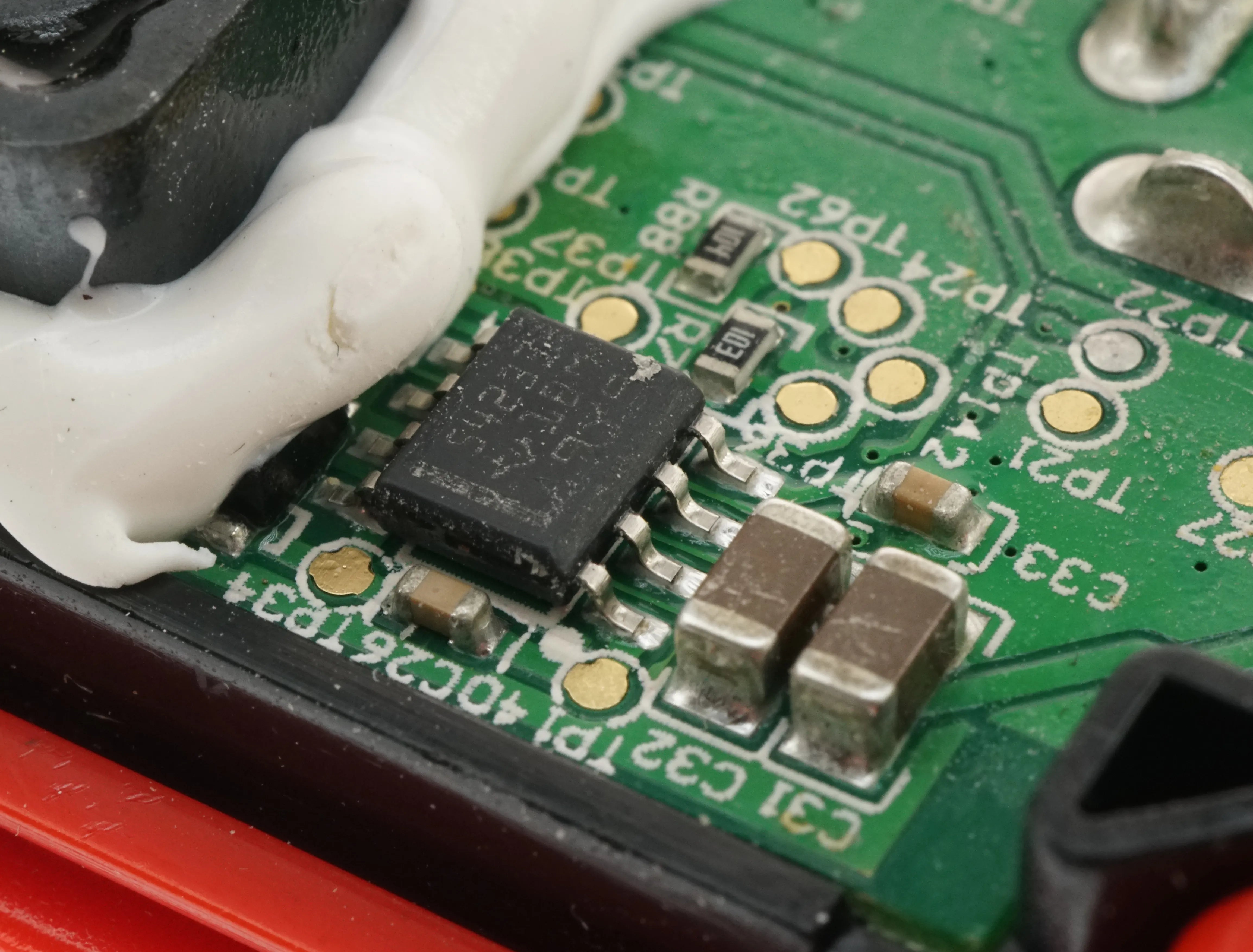
This is the control power section of the circuit board - featuring a large inductor and a Texas Instruments TPS54233 Step Down DC-DC Converter IC. Datasheet here
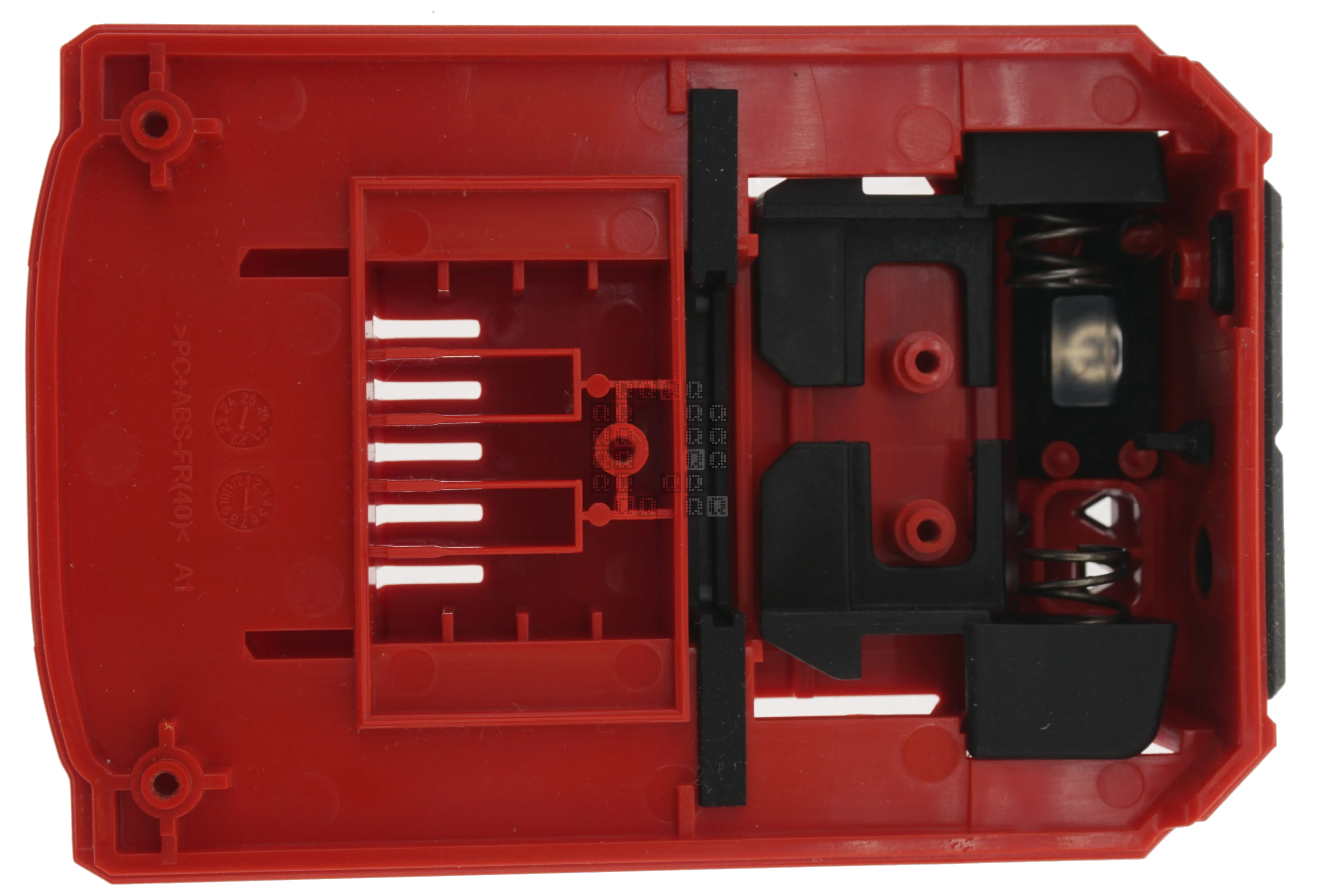
And this is the impossible to re-assemble latching mechanism found inside the tool end cap. It came apart so easily, yet I can't get it back together.
I'm going to stop here on this post. There is a lot more information to be gotten here, but my time is limited on putting it in a readable format.